


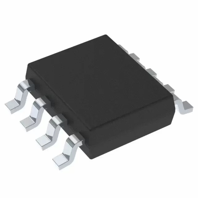

DAC7760IPWPR
Brand: Texas Instruments
Texas Instruments DAC7760IPWPR is a power management component designed for Industrial Automation and related applications. In stock at Superb Automation — request a quote for competitive pricing and fast delivery.
Product Specifications
DAC7760IPWPR
Texas Instruments — Power Management & Signal Chain
Product Overview
The DAC7760IPWPR from Texas Instruments is a power management / signal chain IC delivering high efficiency, precision regulation, and robust protection. Texas Instruments (TI) is a global leader in analog ICs, power management solutions, and embedded processors.
Superb Automation partners with leading brands including Qorvo, TI, ADI, XILINX, NVIDIA, Intel, ST, MACOM, Renesas, and Coilcraft to provide complete BOM and supply-chain solutions.
Key Features
- High-efficiency power conversion with low quiescent current
- Wide input voltage range with precision output regulation
- Integrated over-current, over-temperature, and short-circuit protection
- Small footprint packaging for space-constrained designs
- AEC-Q100 qualified options available for automotive applications
- Flexible sequencing and soft-start control
Key Specifications
| Input Voltage | V |
| Output Voltage | V |
| Output Current | A |
| Switching Frequency | kHz |
| Efficiency | % |
| Quiescent Current | µA |
| Topology | — |
| Package | — |
| Operating Temp | °C |
| Protection | — |
Applications
Industrial Automation
Automotive Electronics
Telecom Infrastructure
Server & Data Center Power
Medical Devices
Consumer Electronics
Request Quote — In Stock, 100% New & Original, Full Warranty
DAC7760IPWPR: the 12-bit current and voltage output converter for a 4-20 mA loop
The DAC7760IPWPR is the 12 bit member of the DACx760 pair, a single channel converter that drives a 4 to 20 mA current loop and a voltage output from one die. The vendor carries the family as ACTIVE and lists current ranges of 4 to 20 mA, 0 to 20 mA and 0 to 24 mA, voltage ranges of 0 to 5 V and 0 to 10 V with a 10 per cent overrange, simultaneous current and voltage output from one data register, 0.1 per cent of full scale total unadjusted error maximum, an internal 5 V reference at 10 parts per million per degree, an internal 4.6 V supply, a CRC check and watchdog timer, a thermal alarm, an open circuit alarm and a short circuit current limit, over minus 40 to plus 125 degrees.
The pair differs in resolution and nothing else that matters to a purchase order. The 16 bit member is the DAC8760, the 12 bit member is the DAC7760, and both share the same 24 pin HTSSOP and the same 40 pin VQFN. A customer who has been quoting the 16 bit string into a loop that only needs 12 bits is paying for resolution that the loop cannot use, and that is a common line item to correct during a BOM review.
The DAC7760IPWPR rows as the addendum publishes them
| Part class | Single channel 12 bit current and voltage output converter |
| Vendor status | ACTIVE, production data |
| Data sheet | SBAS528D, June 2013, revised December 2021 |
| Current ranges | 4 to 20 mA, 0 to 20 mA, 0 to 24 mA |
| Voltage ranges | 0 to 5 V, 0 to 10 V, and 10 per cent overrange |
| Total unadjusted error, voltage | 0.1 per cent of full scale maximum |
| Total unadjusted error, current | 0.2 per cent of full scale over temperature |
| Differential nonlinearity | 1 LSB maximum, monotonic |
| Integral nonlinearity, voltage | 0.04 per cent of full scale over temperature |
| Integral nonlinearity, current | 0.08 per cent of full scale over temperature |
| Internal reference | 5 V, 10 parts per million per degree maximum |
| Reference input window | 4.95 V to 5.05 V external |
| External reference current | 30 microamps |
| Internal supply output | 4.6 V for the digital side |
| Loop compliance | Supply minus 2 V at 24 mA |
| Settling, current | 10 microseconds for a 16 mA step to 0.1 per cent |
| Settling, voltage | 22 microseconds for 0 to 10 V, 13 for 0 to 5 V |
| Slew rate | 0.5 volts per microsecond, programmable by register |
| Output headroom | 0.5 V above and below the output swing |
| Voltage load | 1 kilohm for specified performance |
| Short circuit current | 30 mA |
| Body, HTSSOP | 24 pins, 7.80 by 4.40 millimetres |
| Body, VQFN | 40 pins, 6.00 by 6.00 millimetres |
| Reel row, HTSSOP | DAC7760IPWPR, 2000 pieces, large tape and reel |
| Reel row, VQFN | DAC7760IRHAR, 2500 pieces, large tape and reel |
| Moisture level | Level 3 at 260 degrees, 168 hour floor life |
Two rows decide the board rather than the part. The HTSSOP reel is 2000 pieces and the VQFN small reel is 250 pieces with the large reel at 2500, so a prototype built from the 40 pin body arrives in a 250 piece small reel and a production build in a 2500 piece reel. The moisture level 3 rating also matters, because a level 3 part has a 168 hour floor life after the bag is opened and a board that sits on a bench over a weekend is outside it.
What the electrical table fixes
The current output carries a tighter headline than the voltage output, 0.1 per cent against 0.2 per cent of full scale, and both are quoted with the internal reference in use. At 20 mA a 0.2 per cent error is 40 microamps, which is a quarter of a 12 bit LSB of 4.9 microamps, so the digital resolution and the analogue accuracy are not in the same class and a loop calibrated to 12 bits cannot be better than the 40 microamp figure without a calibration step in the end system.
The loop compliance figure is the one that catches people. The current output can hold 24 mA only while the supply sits 2 V above the loop voltage, so a 24 V supply with a 500 ohm loop resistor at 20 mA, which is 10 V, is comfortable, while a 24 V supply and a 1 kilohm loop at 20 mA, which is 20 V, leaves 2 V and no margin. The 10 V to 36 V supply range in the description is the headline, and the compliance row is what turns it into a working circuit.
The settling figures separate the two outputs by a factor of two. Ten microseconds for a 16 mA step and 22 microseconds for a 0 to 10 V step mean a loop that switches between current and voltage modes cannot use one number for both, and a HART signal superimposed on the current output needs the current settling figure plus the bandwidth of the coupling network. The 0.5 volt per microsecond slew rate and the register programmable slew limit are the two controls that keep a step from disturbing a HART channel.
Where the body fits on a board
The 24 pin HTSSOP at 7.80 by 4.40 millimetres is the body with the thermal pad and the easier rework, and it is the one that suits a 4 to 20 mA transmitter module that has to dissipate the loop current somewhere. The 40 pin VQFN at 6.00 by 6.00 millimetres carries the same die in a smaller outline and is the choice when the board is dense and the thermal path goes through the pad into a plane. Both bodies are rated to the same junction temperature and both are level 3 at 260 degrees.
The part is a single channel device with a watchdog, a CRC and a thermal alarm, and those three features exist because the application is a process loop that must fail to a known state rather than to a random one. A board that ignores the alarm pin and the watchdog has paid for the features and not used them. The vendor recommends a 100 picofarad capacitor to ground on the comparator pin in the revision note, and that is the sort of detail that appears in a revision history rather than in a feature list.
What the documents do not publish
The product page gives total unadjusted error at three temperatures and no long term drift figure for the current output beyond a drift against time row in the electrical table, which is quoted at 125 degrees over 1000 hours for the voltage output. It gives no output noise density and no crosstalk figure, which matters less on a single channel part and more when several channels sit on one board. The page also does not print the register map, so a customer who needs to know the power up state of every block has to open section eight of the document.
The compliance figure is printed as a supply relationship rather than as a curve, and the current output has a settling figure at 25 degrees only in the dynamic table. A transmitter that runs at 85 degrees in a cabinet should read the over temperature rows before accepting the 10 microsecond number, because the amplifier that drives the loop is the first block to slow down as the die warms.
Second source and long term availability
A 4 to 20 mA transmitter with an integrated reference and a watchdog is a narrow class and the crosses are fewer than they are for a plain converter. The candidates that exist differ in the compliance voltage, the HART coupling and the register map, so a cross is a board change in most cases. The ADC DAC cross reference page sets out what we compare, and the obsolete part cross reference hub page covers the case where the part is no longer offered.
The family has been in production since 2013 and the current revision is dated 2021, with the addendum rows current. Both bodies are ACTIVE across 2000 and 2500 piece reels. The status column is a vendor statement as of the document date and it is not a supply commitment, so a ten year programme should ask for a written statement rather than read the column.
What to send with an enquiry
Send the exact string, the body, the quantity and the date you need it. State the loop supply, the loop resistance and the maximum loop current, because those three decide whether the compliance row is met. State whether HART is superimposed and whether the voltage output is used at the same time as the current output.
Send the calibration plan as well. A 0.1 per cent part in a 12 bit system is limited by the end calibration, not by the converter, and a customer who expects the part alone to hold 12 bits will not get it. The BOM scrubbing page explains how we reconcile a line like this against the build quantity before a schedule is confirmed.