


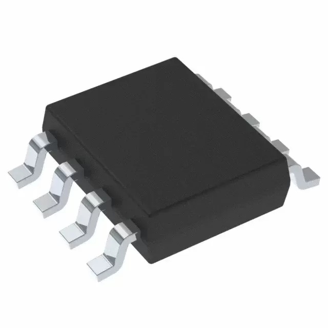

CD4053BM96
Brand: Texas Instruments
Texas Instruments CD4053BM96 is a power management component designed for Industrial Automation and related applications. In stock at Superb Automation — request a quote for competitive pricing and fast delivery.
Product Specifications
CD4053BM96
Texas Instruments — Power Management & Signal Chain
Product Overview
The CD4053BM96 from Texas Instruments is a power management / signal chain IC delivering high efficiency, precision regulation, and robust protection. Texas Instruments (TI) is a global leader in analog ICs, power management solutions, and embedded processors.
Superb Automation partners with leading brands including Qorvo, TI, ADI, XILINX, NVIDIA, Intel, ST, MACOM, Renesas, and Coilcraft to provide complete BOM and supply-chain solutions.
Key Features
- High-efficiency power conversion with low quiescent current
- Wide input voltage range with precision output regulation
- Integrated over-current, over-temperature, and short-circuit protection
- Small footprint packaging for space-constrained designs
- AEC-Q100 qualified options available for automotive applications
- Flexible sequencing and soft-start control
Key Specifications
| Input Voltage | V |
| Output Voltage | V |
| Output Current | A |
| Switching Frequency | kHz |
| Efficiency | % |
| Quiescent Current | µA |
| Topology | — |
| Package | — |
| Operating Temp | °C |
| Protection | — |
Applications
Industrial Automation
Automotive Electronics
Telecom Infrastructure
Server & Data Center Power
Medical Devices
Consumer Electronics
Request Quote — In Stock, 100% New & Original, Full Warranty
CD4053BM96: three changeover switches on a 2500 piece SOIC reel
The CD4053BM96 is the small outline reel member of the CD4053B family, three single pole double throw analogue switches with independent control pins on one die. The vendor marks the family ACTIVE and describes it as a 20 V, 2 to 1, three channel analogue multiplexer with logic level conversion. The parametric table gives three channels, a 2 to 1 configuration, single supply options of 5, 12, 16 and 20 V, dual supply options of plus or minus 2.5, 5 and 10 V, a typical on resistance of 125 ohms, an on capacitance of 9 picofarads, a bandwidth of 30 MHz and a 10 milliamp continuous channel current.
The row reads Active, SOIC body with 16 leads at 59.4 square millimetres, 2500 pieces on a large tape and reel, RoHS yes, nickel palladium gold finish, moisture level 1 at 260 degrees with unlimited floor life, minus 55 to plus 125 degrees and the marking CD4053M. That marking is the first thing to notice: it is shorter than the orderable string and it does not carry the B. A line that inspects incoming parts against a drawing which expects CD4053BM will see CD4053M and query it, and the query is correct in the sense that the top mark and the orderable string are not the same string.
The CD4053BM96 row as the vendor addendum publishes it
| Part class | Triple 2 to 1 analogue switch with independent controls |
| Vendor document | SCHS047O, revised May 2026, CD4051B, CD4052B and CD4053B |
| Package for this code | SOIC (D), 16 leads, 59.4 square millimetres at 9.9 by 6 mm |
| Packing | 2500 pieces on a large tape and reel |
| Status | Active, production |
| RoHS | Yes |
| Lead finish | NIPDAU |
| Moisture level | Level 1 at 260 degrees, unlimited floor life |
| Part marking | CD4053M |
| Sibling row | CD4053BM96.A, same body and quantity |
| Obsolete SOIC rows | CD4053BM, CD4053BMT, CD4053BM96G3 |
| SOP reel row | CD4053BNSR, 2000 pieces |
| TSSOP reel row | CD4053BPWR, 2000 pieces, marking CM053B |
| Obsolete TSSOP rows | CD4053BPW, CD4053BPWRG3, CD4053BPWRG4 |
| PDIP row | CD4053BE, 25 pieces in a tube |
| Ceramic rows | CD4053BF, CD4053BF.A, CD4053BF3A, CD4053BF3A.A |
| Military drawing row | 8101801EA, CDIP, 25 pieces |
| Configuration | 2 to 1 single pole double throw, three channels |
| Digital range | 3 V to 20 V, independent of the analogue rails |
| On resistance | 125 ohms typical at 15 V |
| Capacitance and bandwidth | 9 pF typical, 30 MHz |
| Leakage | Plus or minus 10 pA typical at 15 V |
Three independent controls on a scan card
A 4053B on a scan card does a job that neither of the other two parts can do: it lets each of three separate paths be switched on its own schedule. One switch can route a reference to a converter, a second can short a filter capacitor, and a third can disconnect a transducer while a calibration is applied. All three sit in one 16-lead body with three control lines that the controller drives directly, and there is no decoding to work around.
The cost of that independence is pin count: three switches need six channel pins, three control pins, two supply pins and a ground, which fills the 16 leads exactly. A mixing console that has to route a stereo pair while it mutes a monitor send uses all three switches at once, and each one moves on its own control line with no shared decoding to sequence around. A test fixture that switches a load between two meters while it shorts a calibration resistor is the same pattern in a different industry, and it is the pattern this part was built for. Adding independent control to a 4052B would need two more pins and a bigger body, which is why the family is three parts rather than one configurable device.
Marking, traceability and incoming inspection
CD4053M on the body against CD4053BM96 on the reel label is normal for this family and it is the kind of mismatch that fails a first article inspection. The right response is not to reject the lot but to confirm the marking row in the addendum before the inspection plan is written, because the plan should be checking the marking the vendor publishes rather than the marking the drawing implies.
The same applies to the SOP and TSSOP bodies, which carry CD4053B and CM053B respectively. Three bodies, three marks, and one die behind all three of them. A receiving inspection that has one field for marking will produce a finding on two of the three rows every time.
Break before make on a changeover switch
A changeover switch is used in two very different ways. In a routing application the two throws carry different sources and must never be connected, so break before make is a requirement and the brief open interval is harmless. In a current path the same part is used to swap a load between two supplies, which is a much harder job: the load current has to be interrupted and re-established, and the switch is not rated for the inductive kick that follows.
The vendor publishes break before make as a feature and does not publish a make before break option in this family. A board that needs a make before break changeover, for example to keep a supply alive while switching sources, is using the wrong part, and the right part is a dedicated power multiplexer with the sequencing built in. The same reasoning applies to the continuous current rating, which is ten milliamps per channel and belongs to the conducting path rather than to whatever sits upstream or downstream of the switch.
The other three bodies of the same function
A changeover switch that has to fit a different board can move between four bodies without changing anything electrical: the plastic DIP at 181.42 square millimetres, the SOP at 79.56, the SOIC at 59.4 and the TSSOP at 32. The DIP ships in a 25 piece tube, the SOP and TSSOP in 2000 piece reels, and the SOIC in this 2500 piece reel. The choice is board area against process, exactly as it is in the rest of the family.
What varies by body beyond the footprint is the marking, and the marking is what a receiving inspection reads. The SOIC row is CD4053M, the SOP row is CD4053B, the TSSOP row is CM053B and the DIP is CD4053BE in full. Four rows, four marks, one die. A purchasing system that stores one approved marking and buys across four bodies will generate a non conformance on three of them, and the cure is a marking field per row rather than a single text field on the part master.
Reel planning and the obsolete tube
With CD4053BM obsolete, the 2500 piece reel is the only SOIC format, and the SOP and TSSOP rows at 2000 pieces are the alternatives that need a different footprint. For a build of 500 boards with one switch each, the reel is a fifth used and the remainder is a stock decision. For a build of 3000, the reel is the natural unit and the question disappears.
The last time buy and LTB planning page covers how a family that has already closed three surface mount rows is planned for the next closure, and the date code management page covers how a partial reel is rotated against the builds that will consume it.
What to send with an enquiry
Send the string, the analogue rails, how many of the three switches are used and the annual quantity. If the drawing expects the long marking rather than CD4053M, say so, because the marking row is the one an inspection plan is written from. If the board can move to a 12 V single rail, the TMUX4053 replacement can be quoted as an alternative, and the pin to pin cross reference page sets out what that move changes.