
TPS2514AQDBVRQ1
Brand: Texas Instruments
Texas Instruments TPS2514AQDBVRQ1 is a power management component designed for AI Servers & Low-Altitude Economy (Drone and UAV) and related applications. In stock at Superb Automation — request a quote for competitive pricing and fast delivery.
Product Specifications
TPS2514AQDBVRQ1
Texas Instruments — Power Management & Signal Chain
Product Overview
The TPS2514AQDBVRQ1 from Texas Instruments is a power management / signal chain IC delivering high efficiency, precision regulation, and robust protection. Texas Instruments (TI) is a global leader in analog ICs, power management solutions, and embedded processors.
Superb Automation partners with leading brands including Qorvo, TI, ADI, XILINX, NVIDIA, Intel, ST, MACOM, Renesas, and Coilcraft to provide complete BOM and supply-chain solutions.
Key Features
- High-efficiency power conversion with low quiescent current
- Wide input voltage range with precision output regulation
- Integrated over-current, over-temperature, and short-circuit protection
- Small footprint packaging for space-constrained designs
- AEC-Q100 qualified options available for automotive applications
- Flexible sequencing and soft-start control
Key Specifications
| Input Voltage | V |
| Output Voltage | V |
| Output Current | A |
| Switching Frequency | kHz |
| Efficiency | % |
| Quiescent Current | µA |
| Topology | — |
| Package | — |
| Operating Temp | °C |
| Protection | — |
Applications
Industrial Automation
Automotive Electronics
Telecom Infrastructure
Server & Data Center Power
Medical Devices
Consumer Electronics
Request Quote — In Stock, 100% New & Original, Full Warranty
TPS2514AQDBVRQ1: automotive USB dedicated charging port controller with a 2.7 V divider signature on both data lines
TPS2514AQDBVRQ1 is a small controller that puts the right voltage signature on a USB data pair so a phone or tablet recognises the port as a dedicated charger and draws full current in a SOT-23 (DBV) body of 6 pins. It holds both data lines at 2.7 V through 30 kOhm output impedances in divider mode, shortens the pair together for the battery charging specification short mode, drives the 1.2 V mode used by some handsets, and switches between the schemes by watching the data line voltages. It draws 155 uA typical and is qualified to AEC-Q100 with HBM level H2 and CDM level C5.
Order code and package
| Ordering string | TPS2514AQDBVRQ1, the six pin SOT-23 body on a 3000 piece large reel |
| Part marking | ZBAW on the automotive body |
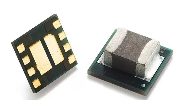
| Body | Six pin SOT-23, 3.23 mm by 3.17 mm including the leads, which fits beside a USB connector |
| Material | RoHS compliant, nickel palladium gold finish, moisture level 1 with unlimited floor life at 260 degrees |
| Sibling | TPS2513A-Q1 is the two port version on the same die, and the A suffix is the 2.7 V on both lines variant rather than 2.7 V and 2.0 V |
| Qualification | AEC-Q100 qualified, with ESD classification H2 on the human body model and C5 on the charged device model |
| Temperature | minus 40 to 125 degrees junction, which is the range the electrical table is specified over |
Electrical parameters that decide the application
| Input range | 4.5 V to 5.5 V, so the part sits directly on the 5 V charging rail and shares it with the port switch |
| Supply current | 155 uA typical and 220 uA maximum, which is small against the charging current but permanent while the port is live |
| Undervoltage lockout | 4.1 V rising with 100 mV of hysteresis, so the signature appears only when the 5 V rail is actually valid |
| Divider mode | Both data lines driven to 2.7 V with a 2.57 to 2.84 V window and 24 to 36 kOhm of output impedance |
| Short mode | The two data lines are tied together through 157 to 200 ohm, which is the resistance the battery charging specification expects a dedicated charger to present |
| Detection threshold | 330 mV on a data line, with 50 mV of hysteresis, below which the part leaves the charging signature and returns to divider mode |
| 1.2 V mode | Both lines held at about 1.2 V, which some handsets read as a charger rather than a host |
| Mode selection | Automatic. The part watches the data line voltages and switches scheme without a control pin, so there is nothing to configure in firmware |
| Output current | The data lines are driven through the impedances above rather than by a hard driver, which is what keeps two ports from fighting if a cable connects them |
| No port power switch | The part sets the signature only. The 5 V port switch and its current limit are separate parts in the same circuit |
| No data pass through | There is no USB data path in this device. A port that has to charge and enumerate needs a hub or a mux beside it |
Family variants and how they differ
| TPS2513A against TPS2514A | Same signature behaviour, one port against two. The two port version is used on a head unit that exposes a pair of sockets and needs a separate signature per socket |
| The A suffix | The 2.7 V and 2.7 V signature is the dividing scheme that Apple and several Android handsets read as a 2 A capable charger. The non A members put 2.7 V on one line and 2.0 V on the other, which is a different scheme with a different current ceiling |
| Short mode | Tying the data pair together is the scheme in the USB battery charging specification, and it is what a device falls back to when it does not recognise anything else. The part enters it automatically when the detection logic decides divider mode is not wanted |
| 1.2 V mode | Some handsets read 1.2 V on both lines as a charger. It is a legacy scheme and the reason the part has three modes rather than one |
| What happens on a data connection | If the far end pulls a data line below 330 mV, the part reads that as a host and returns to divider mode, which stops the port from holding a charger signature while a computer is trying to enumerate |
| No firmware | The mode logic is in hardware. A board that changes the port behaviour has to change the part, not a register |
Points to check before this part goes on a BOM
The signature is the whole function. Without it a handset sees a plain port and limits itself to 500 mA, so the charging current a product advertises depends on this part being present and on the mode it selects.
The output impedances are 30 kOhm nominal with a 24 to 36 kOhm window. A phone that reads the signature by loading the line sees a divider formed with that impedance, so the window is part of the compatibility rather than a tolerance on a voltage only.
The 330 mV detection threshold with 50 mV of hysteresis is what stops the part fighting a host. A cable with a weak pull down may not cross that threshold, and the port then keeps the charger signature while a computer is trying to enumerate it.
The part does not switch the 5 V rail. A port needs a current limited switch and usually a fault protected connector beside this device, and the current that can be delivered is set there rather than by the signature.
Supply current of 155 uA is permanent while the port rail is live. On a vehicle that leaves the USB rail on in a parked car, that current has to be part of the quiescent budget along with the port switch and the connector leakage.
There is no data path. A port that has to charge and also carry USB data needs a hub or a mux, and the signature controller then sits beside it rather than replacing it.
Why a charger needs a signature at all
A USB port is limited to 500 mA by the specification, and a handset that cannot tell what kind of port it is attached to assumes that limit. The result is a product that advertises a 2 A port and charges a phone at 500 mA, which shows up as a support complaint rather than as a circuit fault.
The signature is a voltage pattern on the two data lines. The handset reads it, decides the port is a dedicated charger rather than a computer, and raises its input current. The controller that generates that pattern is a six pin part drawing 155 uA, and it is the difference between a port that charges in an hour and one that takes all afternoon.
Where this order code fits
Charging ports in automotive infotainment head units, rear seat USB outlets, dash cameras and telematics boxes, and any product that has to charge a phone at more than the 500 mA a plain USB port gives. A phone connected to a port with no charging signature limits itself to 500 mA, so the signature is what turns a data port into a charger. Teams comparing it with a neighbouring part start from our Power Management Cross Reference page, and teams replacing a part that has gone end of life start from the Pin to Pin Cross Reference page.
Questions buyers ask
What charging current can this part deliver? None directly. It sets the signature that tells the handset how much current it may draw, and the actual current comes from the 5 V port switch and its limit.
Which handsets see 2 A from this signature? The 2.7 V on both lines divider scheme is read as a high current charger by a number of handsets, and it is the reason the A suffix exists. The exact current still depends on the phone's own charger table.
Does it need firmware or a register setting? No. Mode selection is automatic and there is nothing to program, so a board that changes port behaviour has to change the part.
Can it pass USB data? No. It only drives the data line voltages, so a port that has to charge and enumerate needs a hub or a mux alongside it.
What happens when a computer is connected? If the host pulls a data line below 330 mV the part reads that as a data connection and returns to divider mode, so the charger signature does not block enumeration.
SUPERB holds and sources this line for production and repair demand, quoted against the exact ordering string with date codes, packing and country of origin stated on the offer. When a part is moving, the Component Lead Time Solutions page sets out the checks that keep a substitute from failing on the bench.