
A power rail is the part of a board that is reviewed last and fails first. Power management cross reference work starts when a regulator, a load switch, a hot swap controller or a charger is retired while the board that uses it is still in production. The device is often small, inexpensive and easy to overlook, which is exactly why the replacement is chosen too quickly.
The failure mode differs from a converter. A regulator that looks equivalent can start cleanly on the bench and still oscillate at a temperature corner, or hold regulation perfectly while losing the soft start that kept inrush inside the connector rating.
Where power management cross references fail
The feedback network comes first. Output voltage is set by the reference and the divider, so a device with a different reference voltage turns the existing divider into a different rail. A board specified for 1.2 V can come back at 1.35 V and still look regulated on a meter.
Compensation comes second. A part with an external compensation pin and a part with a fixed internal loop behave differently with the same ceramic output capacitors, and the difference shows up as ringing after a load step rather than as a fault at start up. Switching frequency matters here too, because it sets both the inductor value the board already has and the ripple the load was qualified against.
Protection thresholds come third. Current limit, hiccup mode, over voltage and under voltage lockout are the numbers that decide what happens during a fault, and they are rarely in the headline comparison. A replacement with a higher current limit protects the regulator and stops protecting the connector.
Then sequencing. Enable thresholds, power good polarity, tracking and the order in which rails come up decide whether a processor boots on every cycle or on most of them. A board that sequences two rails correctly in the lab can fail one start in fifty when the replacement has a different enable threshold.
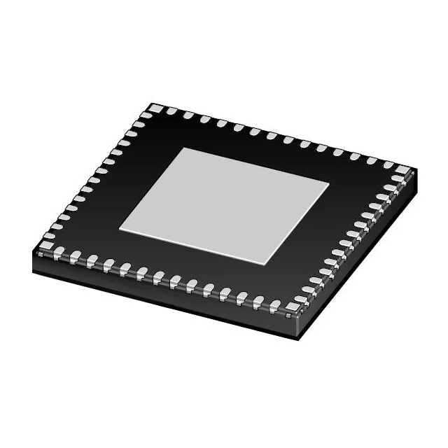
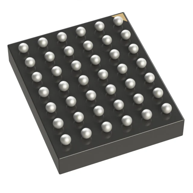
Finally the package. A thermal pad with a different geometry changes the copper area under the part, and a smaller body with the same pin count can still need a new stencil aperture.
The parameters that decide a power management cross reference
| Parameter | Why it decides the outcome | What a weak comparison looks like |
|---|---|---|
| Input range and transient rating | Decides survival on a rail that carries motor or relay transients | Nominal input matched, transient rating not compared |
| Output voltage and reference | Sets the divider and the accuracy over temperature | Same nominal output, reference voltage and tolerance different |
| Current capability and limit | Decides headroom and what the protection actually protects | Output current matched, current limit threshold ignored |
| Switching frequency | Sets inductor value, ripple and the EMI profile already qualified | Frequency assumed close, existing inductor no longer correct |
| Compensation | External or internal loop decides stability with the fitted capacitors | Loop type not compared, ringing appears only after a load step |
| Soft start and inrush | Keeps start up current inside the connector and fuse rating | Soft start not compared, fuse trips on the first cold start |
| Sequencing and enable | Thresholds, power good polarity and tracking decide reliable boot | Rails matched, sequence order different, intermittent boot failure |
| Package and thermal pad | Footprint, pad geometry and thermal resistance decide the copper area | Same pin count, pad and thermal path different from the board |
| Grade and longevity | Temperature grade and remaining production life decide the risk | Commercial grade offered for an engine bay or outdoor unit |
How SUPERB PCBA handles a regulator change
Send the original part number, the rail it produces, the load it feeds and the annual quantity. The reply is a line by line comparison against the table above, with the feedback divider, the compensation, the protection thresholds and the sequencing marked as compatible, needs a check, or needs a board change, and with any point the datasheet leaves open returned as a question plus the condition that closes it.
Where the original is already end of life, the routes are collected in the obsolete part cross reference hub. Regulators and their protection devices sit under power management ICs, and the optical module and instrument families are collected in a power management selection for optical modules. Where a candidate is pin compatible on paper, the procedure in pin to pin cross reference confirms the pin map before anything is ordered.
Provenance comes before the sample. Reels are counted by X-ray, markings are inspected, and decapsulation is used where the risk justifies it. Verified lots carry a 730 day warranty, and a substitution only enters the BOM after written approval from your side.
SUPERB Assembly then measures the rail rather than the part: ripple and load step response on the assembled board, start up and shut down on repeated cycles, sequencing at the temperature corners the product actually sees, and in circuit and functional test on fixtures approved by your team. The work runs under IPC-A-610 Class 2 and Class 3, ISO 9001, and ISO 13485 for medical programmes, with 3D SPI before reflow, 3D AOI after it, X-ray in 2D and CT mode with voiding below 5 percent, and placement down to 01005. Boards in the same build are supported from 500 MHz to 77 GHz, with lines down to 0.05/0.05 mm, impedance held to plus or minus 5 percent and to plus or minus 2 percent where the circuit needs it, and up to 68 layers, so a power section and a radio section are qualified as one build rather than as two purchases.
The report that closes the change
A regulator substitution is closed by data. The file that ends the discussion holds the comparison, the ripple and load step measured at the fitted capacitors, the start up sequence on repeated cycles, and the temperature behind each measurement. SUPERB Tech keeps that file against the build, so the next audit starts from evidence.
Power management cross reference questions
Can a regulator with a higher current rating always replace a smaller one?
Only if the current limit and the compensation still suit the board. A higher rating with a higher limit can leave the connector and the traces unprotected.
Is a fixed output part easier than an adjustable one?
It is simpler to place, and it removes the divider as a variable. Where the rail has to be trimmed, an adjustable part with a compared reference is the safer route.
How is stability proved?
With a load step on the assembled board, at the output capacitors already fitted, and repeated at the temperature corners. A bench measurement at room temperature is the start, not the proof.
What happens when the replacement changes the power good polarity?
It becomes a board change. The receiving device and the reset supervisor are checked together, and the change is quoted with the test plan so the cost is known before the order.
Next step
Send the original regulator or PMIC part number, the rail and load it serves, the board reference and the annual quantity. You get the parameter comparison with each difference marked, the candidate list with availability, and the measurements needed to release the change.