


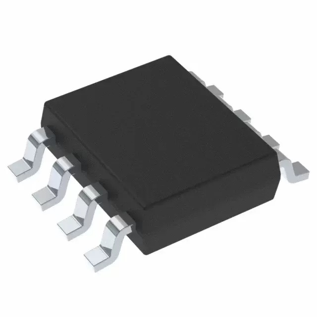

INA186A2IDDFT
Brand: Texas Instruments
Texas Instruments INA186A2IDDFT is a power management component designed for Industrial Automation and related applications. In stock at Superb Automation — request a quote for competitive pricing and fast delivery.
Product Specifications
INA186A2IDDFT
Texas Instruments — Power Management & Signal Chain
Product Overview
The INA186A2IDDFT from Texas Instruments is a power management / signal chain IC delivering high efficiency, precision regulation, and robust protection. Texas Instruments (TI) is a global leader in analog ICs, power management solutions, and embedded processors.
Superb Automation partners with leading brands including Qorvo, TI, ADI, XILINX, NVIDIA, Intel, ST, MACOM, Renesas, and Coilcraft to provide complete BOM and supply-chain solutions.
Key Features
- High-efficiency power conversion with low quiescent current
- Wide input voltage range with precision output regulation
- Integrated over-current, over-temperature, and short-circuit protection
- Small footprint packaging for space-constrained designs
- AEC-Q100 qualified options available for automotive applications
- Flexible sequencing and soft-start control
Key Specifications
| Input Voltage | V |
| Output Voltage | V |
| Output Current | A |
| Switching Frequency | kHz |
| Efficiency | % |
| Quiescent Current | µA |
| Topology | — |
| Package | — |
| Operating Temp | °C |
| Protection | — |
Applications
Industrial Automation
Automotive Electronics
Telecom Infrastructure
Server & Data Center Power
Medical Devices
Consumer Electronics
Request Quote — In Stock, 100% New & Original, Full Warranty
INA186A2IDDFT: the 50 V/V small reel code the addendum marks obsolete
INA186A2IDDFT is the 50 V/V member of the family in the eight pin thin body with a T suffix that stands for a small reel. The electrical rows are the same as the large reel code: 50 V/V, 120 dB of rejection, 50 microvolts of maximum offset, 48 microamps of quiescent current and the same 1.7 to 5.5 volt supply.
The carrier is where this code needs attention. The vendor addendum read for this page prints INA186A2IDDFT with the status Obsolete and no packing quantity, while INA186A2IDDFR, the same body on a 3000 piece large reel, is active. A build that has the T suffix on its bill of materials is therefore ordering a row the vendor no longer packs, and the page says so rather than quoting a reel size that is not published.
INA186A2IDDFT as the vendor document publishes it
| Gain | 50 V/V fixed |
| Gain error | 0.04 per cent typical, 1 per cent maximum |
| Gain error drift | 2 ppm per degree typical, 10 maximum |
| Nonlinearity | 0.01 per cent typical of full scale |
| Offset voltage | 3 microvolts typical, 50 microvolts maximum, referred to the input |
| Offset drift | 0.05 microvolts per degree typical, 0.5 maximum |
| Input bias current | 0.5 nanoamps typical, 3 nanoamps maximum |
| Input offset current | 70 picoamps typical |
| Common mode rejection | 120 dB minimum, 150 typical, measured over minus 40 to plus 125 degrees |
| Power supply rejection | 1 microvolt per volt typical, 10 maximum |
| Reference rejection | 0.01 per cent typical, 10 microvolts per volt maximum |
| Common mode range | minus 0.2 volts to plus 40 volts, independent of the supply |
| Supply range | 1.7 volts to 5.5 volts |
| Quiescent current | 48 microamps typical, 65 maximum, 90 over temperature |
| Shutdown current | 10 nanoamps typical, 100 maximum |
| Bandwidth | 45 kHz at 25 V/V, 37 kHz at 100 V/V, 35 kHz at 500 V/V, intermediate options between those |
| Slew rate | 0.3 volts per microsecond |
| Settling to 1 per cent | 30 microseconds from a current step |
| Voltage noise | 75 nanovolts per root hertz |
| Swing to the positive rail | 20 millivolts typical, 40 maximum into 10 kohm |
| Swing to ground | 0.05 millivolts typical, 1 maximum |
| Zero current output | 2 millivolts typical, 10 maximum with the reference grounded |
| Stable load capacitance | 1 nanofarad |
| Temperature range | minus 40 to plus 125 degrees |
| Vendor status | obsolete in the package addendum, no packing quantity printed |
| Catalogue code | INA186A2IDDFT |
| Vendor string | INA186A2IDDFT, obsolete; INA186A2IDDFR is the active row |
| Body | SOT-23 thin, DDF, eight pin |
| Direction | bidirectional, reference pin available |
Which body carries the reference pin and which carries the enable pin
INA186A2IDDFT is offered in three bodies and they are not interchangeable on function. The SC70 holds the reference pin and no enable. The SOT-23 thin body holds both. The DSBGA holds the enable and ties the reference node to ground inside the package, which makes it a one direction part.
The last point is the one to catch before a board is released, because the difference does not appear in an electrical table that is quoted at a mid rail reference. A channel that has to read current in both directions needs the reference pin to lift the output at zero current, and a DSBGA cannot do it. The gate runs the other way: a channel that has to be powered down between readings needs the enable pin, and the SC70 does not have one. Choose the body from those two functions first and from the footprint second, since all three are small enough that the footprint is rarely the reason.
Five fixed gains from 25 to 500 in one body
INA186A2IDDFT is one gain option of a family that shares a die, a pinout and a 1.7 to 5.5 volt supply. A1 is 25 V/V, A2 is 50, A3 is 100, A4 is 200 and A5 is 500, and the letter is the only thing that changes between the five order codes in the same body.
The option is chosen from the shunt and the converter rather than from a preference. A 10 milliohm shunt carrying 2 amps develops 20 millivolts, which at 25 V/V is 500 millivolts and at 200 V/V is 4 volts, so one shunt fills the useful range of a 3.3 volt converter at one gain and clips it at another. Because the gain error is 1 per cent maximum at every option, the gain buys scale and not accuracy, and the option that puts the working current nearest the top of the converter's span is the one to order.
Fifty microvolts of offset and half a nanoamp of bias
Offset on INA186A2IDDFT is 3 microvolts typical and 50 microvolts maximum referred to the input, with 0.05 and 0.5 microvolts per degree of drift, and the bias current is 0.5 nanoamps typical and 3 nanoamps maximum with an offset current of 70 picoamps. The zero drift architecture is what keeps the drift row small enough to ignore across minus 40 to plus 125 degrees.
The bias row decides whether microamp measurement is possible at all. Three nanoamps flowing in a 1 ohm shunt is 3 nanovolts, which is nothing, and in a 1 megohm path it is 3 millivolts, which is everything. A large shunt is allowed by the low bias, and a large shunt is what turns a microamp current into a signal the converter can resolve: 100 microamps in 1 ohm is 100 microvolts, which at 200 V/V is 20 millivolts, a real code on any converter.
Where a zero drift shunt monitor earns its place
INA186A2IDDFT suits four kinds of channel: a battery instrument that sleeps between readings and has to wake with the same offset it had before, a charger whose current loop closes through the monitor, a server or baseband supply where a 40 volt bus has to be measured from a 3.3 volt rail, and a test fixture that measures microamps through a large shunt.
It stops at three things. The output is a fixed gain, so a channel whose current range spans more than one converter decade needs a different gain option or a second path. The input window stops at 40 volts, which rules out a 48 volt telecom bus without a divider that then carries its own error. And the part is a shunt monitor rather than an isolated one, so a high side measurement on a mains referenced rail needs an isolator behind it. Our amplifier cross reference page lists the members of the family side by side, and the drop in replacement check page covers the rows to compare before one gain option is written in place of another.
Minus 0.2 to plus 40 volts of common mode on a 1.7 volt supply
The input of INA186A2IDDFT is specified from 0.2 volts below ground to 40 volts above it, and the window is independent of the supply. A 3.3 volt rail can therefore measure a 40 volt bus, and the negative end matters on a low side shunt where the ground return lifts by a diode drop or by the voltage across a trace.
Inside the window the rejection is 120 dB minimum and 150 typical, measured with no differential signal across the inputs. Outside it the part does not stop working, it stops being specified, and the current through the input protection becomes the error. That is why a bus that can ring above 40 volts needs a series resistor on both inputs rather than a larger shunt, and why the 40 volt figure belongs in the requirements rather than in the notes.
One hundred and twenty decibels of rejection against a fixed noise floor
The rejection of INA186A2IDDFT is 120 dB minimum, so a 1 volt swing on a 40 volt common mode becomes 1 microvolt at the input. The voltage noise density is 75 nanovolts per root hertz, so a 10 kHz bandwidth carries 7.5 microvolts of noise and a 1 kHz bandwidth carries 2.4 microvolts.
Read together, the two rows say that rejection is worth exactly what the bandwidth allows. A channel filtered to 1 kHz sees 2.4 microvolts of noise and 1 microvolt of rejection error, and neither dominates. A channel that runs the full 45 kHz at the A1 gain sees 16 microvolts of noise, and the rejection error disappears into it. The practical conclusion is to filter between the amplifier and the converter rather than to look for more rejection, and to compute the noise on the bandwidth that actually reaches the converter rather than on the small signal figure.
Where a small reel row has been withdrawn, the choice is the large reel or the smaller body that still publishes a 250 piece carrier. Our obsolete part cross reference hub covers that route, and the pin to pin page covers the bodies that share this die.
Is the part itself obsolete? The die is not. The addendum marks this particular order code obsolete with no packing quantity; the same die in the same body on the large reel is active, and the smaller bodies are active on both reel sizes.
What should go on the purchase order? INA186A2IDDFR for a line quantity, or INA186A2IDCKT for 250 pieces in the SC70 body if the reference pin is still needed and the enable is not.