


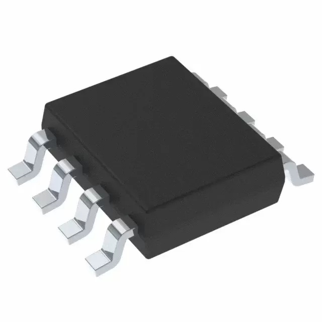

AM26C32IPWR
Brand: Texas Instruments
Texas Instruments AM26C32IPWR is a power management component designed for Industrial Automation and related applications. In stock at Superb Automation — request a quote for competitive pricing and fast delivery.
Product Specifications
AM26C32IPWR
Texas Instruments — Power Management & Signal Chain
Product Overview
The AM26C32IPWR from Texas Instruments is a power management / signal chain IC delivering high efficiency, precision regulation, and robust protection. Texas Instruments (TI) is a global leader in analog ICs, power management solutions, and embedded processors.
Superb Automation partners with leading brands including Qorvo, TI, ADI, XILINX, NVIDIA, Intel, ST, MACOM, Renesas, and Coilcraft to provide complete BOM and supply-chain solutions.
Key Features
- High-efficiency power conversion with low quiescent current
- Wide input voltage range with precision output regulation
- Integrated over-current, over-temperature, and short-circuit protection
- Small footprint packaging for space-constrained designs
- AEC-Q100 qualified options available for automotive applications
- Flexible sequencing and soft-start control
Key Specifications
| Input Voltage | V |
| Output Voltage | V |
| Output Current | A |
| Switching Frequency | kHz |
| Efficiency | % |
| Quiescent Current | µA |
| Topology | — |
| Package | — |
| Operating Temp | °C |
| Protection | — |
Applications
Industrial Automation
Automotive Electronics
Telecom Infrastructure
Server & Data Center Power
Medical Devices
Consumer Electronics
Request Quote — In Stock, 100% New & Original, Full Warranty
AM26C32IPWR: quad RS-422 differential line receiver in the 16-pin TSSOP
AM26C32IPWR is the receive end of a 5 V balanced link, with a fail-safe rule for an open cable in a TSSOP body of 16 pins. The part is a quadruple differential receiver that meets TIA/EIA-422-B, TIA/EIA-423-B and ITU recommendations V.10 and V.11, with three-state outputs and a common enable. It accepts a 7 V common mode range with 200 mV of sensitivity and 60 mV of hysteresis, converts in 17 ns typical, and drives its outputs high when the inputs are open.
Order code and package
| Order code | AM26C32IPWR |
| Function | quad differential line receiver, three-state outputs |
| Standard | TIA/EIA-422-B, TIA/EIA-423-B, ITU V.10 and V.11 |
| Enable | common to all four receivers, active high or active low |
| Package | TSSOP, 16 pins, 5.00 mm by 4.40 mm |
| Temperature grade | I, minus 40 to plus 85 C |
| Supply | single 5 V rail |
| Quiescent current | 10 milliamps typical |
| Fail-safe | outputs high when the inputs are open |
| Datasheet | SLLS187 revision M |
| Predecessor | replaces the AM26LS32 with about one fifth of its power |
Electrical parameters that decide the application
| Common mode range | 7 V, with 200 mV of differential sensitivity across it |
| Hysteresis | 60 mV typical, three times the 20 mV of a bare comparator pair |
| Propagation delay | 17 ns typical |
| Quiescent current | 10 milliamps typical, which is a hundred times the driver beside it |
| Fail-safe rule | an open input produces a high output, so a disconnected cable reads as a marking state rather than as noise |
| Enable | one input pair for the whole package |
| Output | three-state, so the receiver can sit on a bus |
| Supply | 5 V rail, no separate logic supply |
| Input protection | the differential inputs survive the fault voltages of the standard, which is what makes a field connector safe |
| Process | bipolar and CMOS combined, which is where the lower supply current against the older part comes from |
Points to check before this part goes on a BOM
Ten milliamps of quiescent current on the receiver against 100 microamps on the driver is the imbalance that decides the rail budget of a link. A board with one driver and four receivers spends its current in the receivers, and a lower power receiver is worth more than a lower power driver.
Sixty millivolts of hysteresis is the number that keeps a slow or terminated-undriven pair from oscillating at the output. The 3.3 V member of the family specifies 35 mV, so a substitution across the two changes the noise immunity of the receive path even when the pinout matches.
The fail-safe rule covers open inputs. It does not by itself cover a terminated pair with no driver, where the differential voltage is zero rather than absent, so a bus that can lose its driver still needs bias resistors or a receiver that specifies a true fail-safe window.
Seven volts of common mode range with 200 mV of sensitivity is a wide window, but the differential threshold still applies: a pair carrying 150 mV of signal at the far end of a long cable sits below the specified sensitivity and the receiver output becomes a random function of noise.
The enable is common to all four receivers, so a board that wants two receivers live and two tri-stated cannot do it in one package. Gating the outputs externally adds a buffer and a propagation delay.
Seventeen nanoseconds typical of propagation is slower than the 7 ns of the driver beside it, so the round trip through a cable is dominated by the cable at any realistic length and by the receiver at very short ones.
Where this order code fits
Boards pairing this receiver with a 3.3 V driver should check the threshold and the hysteresis before mixing the two families. Boards comparing it with a neighbouring part start from our Pin to Pin Cross Reference page, and boards replacing a part that has gone end of life start from the How to Verify a Drop in Replacement page.
Questions buyers ask
Does an open cable produce a defined output? Yes, the outputs go high when the inputs are open. A terminated pair with no driver is a different case and needs bias resistors.
Why does the receiver draw more current than the driver? The quiescent figures are 10 milliamps against 100 microamps, so four receivers dominate the rail budget of a link even though the driver does the work.
SUPERB holds and sources this Texas Instruments line for production and repair demand, quoted against the exact ordering string with date codes, packing and country of origin stated on the offer. When a line is moving, the Component Lead Time Solutions page sets out the checks that keep a substitute from failing on the bench.