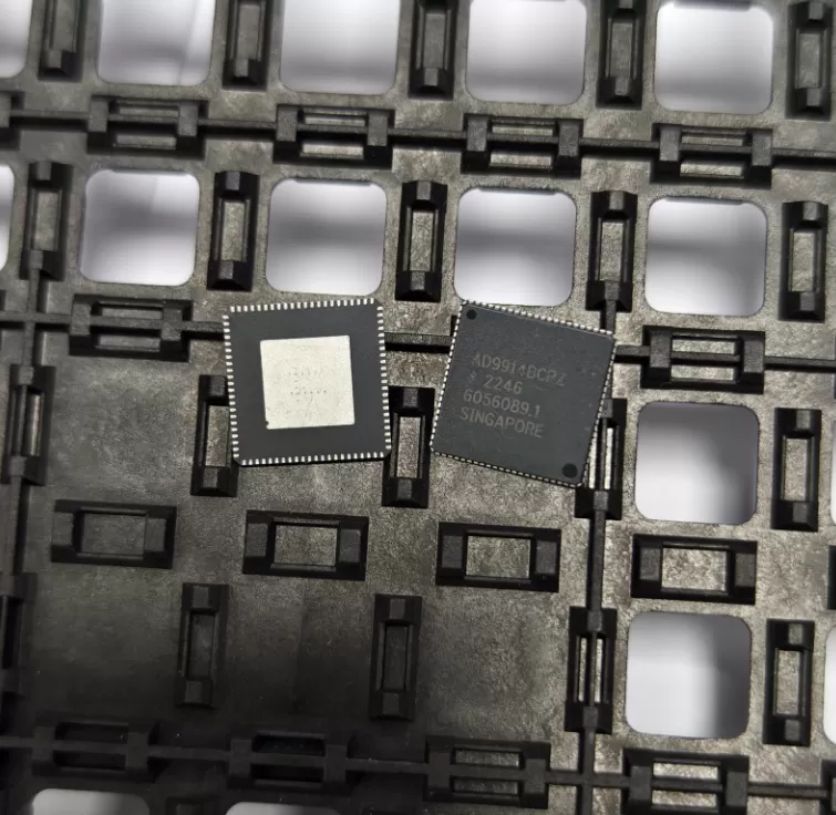
TPS74515PQWDRVRQ1
Brand: Texas Instruments
Texas Instruments TPS74515PQWDRVRQ1 is a power management component designed for AI Servers & Low-Altitude Economy (Drone and UAV) and related applications. In stock at Superb Automation — request a quote for competitive pricing and fast delivery.
Product Specifications
TPS74515PQWDRVRQ1
Texas Instruments — Power Management & Signal Chain
Product Overview
The TPS74515PQWDRVRQ1 from Texas Instruments is a power management / signal chain IC delivering high efficiency, precision regulation, and robust protection. Texas Instruments (TI) is a global leader in analog ICs, power management solutions, and embedded processors.
Superb Automation partners with leading brands including Qorvo, TI, ADI, XILINX, NVIDIA, Intel, ST, MACOM, Renesas, and Coilcraft to provide complete BOM and supply-chain solutions.
Key Features
- High-efficiency power conversion with low quiescent current
- Wide input voltage range with precision output regulation
- Integrated over-current, over-temperature, and short-circuit protection
- Small footprint packaging for space-constrained designs
- AEC-Q100 qualified options available for automotive applications
- Flexible sequencing and soft-start control
Key Specifications
| Input Voltage | V |
| Output Voltage | V |
| Output Current | A |
| Switching Frequency | kHz |
| Efficiency | % |
| Quiescent Current | µA |
| Topology | — |
| Package | — |
| Operating Temp | °C |
| Protection | — |
Applications
Industrial Automation
Automotive Electronics
Telecom Infrastructure
Server & Data Center Power
Medical Devices
Consumer Electronics
Request Quote — In Stock, 100% New & Original, Full Warranty
TPS74515PQWDRVRQ1 1.5 V automotive regulator in the six pin WSON
The TPS74515PQWDRVRQ1 is the fixed 1.5 V member of the TPS745-Q1 family in the six pin WSON body that measures 2 mm by 2 mm with wettable flanks, on a 3000 piece reel. It is the same die and the same 500 mA rating as the eight pin member, in a body with a higher thermal resistance and a smaller land pattern. The code decodes as 1.5 V output, P for the active output discharge, a blank power good letter for the open drain output with a 150 microsecond delay, Q for AEC-Q100 grade 1, W for wettable flanks, DRV for the six pin body and R for the 3000 piece reel.
The 1.5 V point is one of the most common rails on an automotive board, because it sits between the 1.8 V of a memory interface and the 1.2 V of a processor core, and because several camera and sensor devices specify it directly. This body is the one to use when the rail is a few hundred milliamps and the board has no room for the larger land pattern.
Key parameters from the SBVS355C document
| Input range | 1.5 V to 6.0 V |
| Output | 1.5 V fixed, family covers 0.65 V to 5.0 V in 50 mV steps |
| Current | 500 mA continuous, current limit 515 to 865 mA with 720 mA typical |
| Accuracy | Plus or minus 0.85 percent at 25 degrees, plus or minus 1.5 percent maximum over temperature |
| Dropout | 180 mV typical and 265 mV maximum at 500 mA in the 1.5 to 1.8 V output band |
| Quiescent current | 25 microamp typical, 1.5 microamp in shutdown |
| Rejection | 45 dB at 100 kHz |
| Output capacitor | 1 microfarad ceramic or larger for stability |
| Thermal resistance | 80.3 degrees per watt junction to ambient in the six pin WSON, against 55.5 in the eight pin VSON |
| Qualification | AEC-Q100 grade 1, minus 40 to 125 degrees ambient, junction to 150 degrees |
| Package | DRV six pin WSON, 2 mm by 2 mm, wettable flanks |
| Order code | TPS74515PQWDRVRQ1, 3000 pieces on a large reel, level 1, unlimited floor life |
Two millimetres square has a thermal price
The six pin body is 80.3 degrees per watt against 55.5 for the eight pin, a 45 percent penalty that comes from the smaller die pad and the smaller copper connection. At 500 mA and 1.5 V out from a 3.3 V input the part burns 0.9 W, which is a 72 degree rise and a junction at 157 degrees on a 85 degree board, above the 150 degree rating. At 250 mA the same rail burns 0.45 W and the rise falls to 36 degrees.
That is not a reason to avoid the part, it is a reason to run the calculation for each rail. A camera rail that draws 200 mA and sits on a board with a ground plane is a comfortable application. A rail that has to deliver the full 500 mA continuously from a 5 V bus in a sealed enclosure is not, and the eight pin body or a switching regulator is the answer.
Level 1 floor life on this body
The addendum rows for the six pin DRV body print level 1 with unlimited floor life, while the eight pin DRB body of the same family prints level 2 with a one year floor life. So the smaller body is the easier one to hold on an open line, which is the opposite of what the thermal comparison suggests and is worth knowing when a build is planned around storage rather than heat.
The finish on the rows is tin on the rows that are printed most often, and the wettable flank is what makes the solder joint visible to optical inspection. A board that is inspected visually will show a fillet on the flank; a board that is inspected by x ray will show the pad wetting underneath. Neither changes the electrical behaviour.
Where this part fits
Camera modules, cluster displays, head units and telematics units use this family, and the 1.5 V rail usually feeds the memory interface or the sensor core. Our notes on the automotive reel paperwork are under date code management, and the cross reference route for a rail that has to change body is under power management cross reference.
Before a purchase order, and the questions that come up
Check the input range against the real supply. The part needs 1.5 V minimum at the input, and a 1.5 V output from a 1.5 V input is not regulation, so the effective floor is 1.5 V plus the dropout of 265 mV maximum, which is 1.77 V. A rail fed from a 1.8 V supply has 30 mV of margin at full load and none over temperature, which is a rail that will run marginal in the chamber.
Is the eight pin body a drop in? No, the land pattern is different. The die is the same and the electrical table is shared, so the substitution is a board change with no change in behaviour.
Does the power good output need a pull up? Yes, it is open drain on this row, and the pull up should go to the rail of the device that receives the signal rather than to the regulator's own output, so the signal is low when the output is low.
What happens at a shorted output? The foldback limit brings the current down to between 200 and 400 mA and the thermal shutdown protects the die. The part recovers when the short is removed, and the power good output stays low throughout.