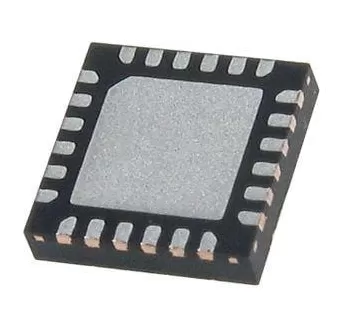

TPS56339DDCR
Brand: Texas Instruments
Texas Instruments TPS56339DDCR is a power management component designed for AI Servers & Low-Altitude Economy (Drone and UAV) and related applications. In stock at Superb Automation — request a quote for competitive pricing and fast delivery.
Product Specifications
TPS56339DDCR
Texas Instruments — Power Management & Signal Chain
Product Overview
The TPS56339DDCR from Texas Instruments is a power management / signal chain IC delivering high efficiency, precision regulation, and robust protection. Texas Instruments (TI) is a global leader in analog ICs, power management solutions, and embedded processors.
Superb Automation partners with leading brands including Qorvo, TI, ADI, XILINX, NVIDIA, Intel, ST, MACOM, Renesas, and Coilcraft to provide complete BOM and supply-chain solutions.
Key Features
- High-efficiency power conversion with low quiescent current
- Wide input voltage range with precision output regulation
- Integrated over-current, over-temperature, and short-circuit protection
- Small footprint packaging for space-constrained designs
- AEC-Q100 qualified options available for automotive applications
- Flexible sequencing and soft-start control
Key Specifications
| Input Voltage | V |
| Output Voltage | V |
| Output Current | A |
| Switching Frequency | kHz |
| Efficiency | % |
| Quiescent Current | µA |
| Topology | — |
| Package | — |
| Operating Temp | °C |
| Protection | — |
Applications
Industrial Automation
Automotive Electronics
Telecom Infrastructure
Server & Data Center Power
Medical Devices
Consumer Electronics
Request Quote — In Stock, 100% New & Original, Full Warranty
TPS56339DDCR: 3 A synchronous buck from 4.5 V to 24 V with a fixed 500 kHz switch and 97 percent duty
TPS56339DDCR is a 3 A synchronous step down converter in a 6 pin SOT-23 that runs from 4.5 V to 24 V, switches at a fixed 500 kHz and holds 97 percent duty for a rail that has to pass the input through in a SOT-23 body of 6 pins. The TPS56339 covers an input of 4.5 V to 24 V and an output of 0.8 V to 16 V at 3 A, with both switches inside the package: 70 milliohms on the high side and 35 milliohms on the low side. Switching is fixed at 500 kHz, loop compensation is internal, soft start is a fixed 5 ms, and shutdown current is 3 uA with a 98 uA quiescent draw. Current limit works cycle by cycle on both switches, and the body is the 6 pin DDC SOT-23.
Order code and package
| Order code | TPS56339DDCR |
| Input voltage | 4.5 V to 24 V |
| Output voltage | 0.8 V to 16 V |
| Rated output current | 3 A |
| Switching frequency | 500 kHz fixed |
| Maximum duty cycle | 97 percent |
| High side switch | 70 milliohm |
| Low side switch | 35 milliohm |
| Soft start | 5 ms internal |
| Package | 6 pin SOT-23, DDC body |
| Document | SLVSEI2A, November 2018, revised May 2019 |
Electrical parameters that decide the application
| Quiescent current, non switching | 98 uA typical |
| Shutdown current | 3 uA typical at VIN 12 V |
| Feedback voltage at 25 C | 0.790 V to 0.802 V to 0.814 V |
| Input UVLO rising | 3.9 V to 4.2 V to 4.4 V |
| Input UVLO falling | 3.5 V to 3.7 V to 3.9 V |
| Enable rising threshold | 1.18 V to 1.28 V |
| Enable falling threshold | 1.08 V to 1.12 V |
| Switch node absolute maximum | 26 V, -3 V on transients under 10 ns |
| Boot to switch absolute maximum | 6 V |
| Thermal parameter junction to top | 9.4 C per W |
| Thermal parameter junction to board | 36.2 C per W |
| Operating junction range | -40 C to 125 C |
Points to check before this part goes on a BOM
A fixed 500 kHz switch sets the whole passive budget. The period is 2 us, so a 24 V to 3.3 V conversion runs a 275 ns on time and a 12 V to 5 V conversion runs 833 ns. An inductor of 4.7 uH to 10 uH keeps the ripple reasonable at those times, and because the loop compensation is inside the part there is no external network to tune, which is why the device is offered in a 6 pin body.
The 70 milliohm and 35 milliohm switches set the conduction loss. At 3 A the low side carries current for most of the cycle in a large step down, so 9 A squared times 35 milliohms is 0.315 W, and the high side adds its share weighted by duty. Total loss around 0.6 W in a SOT-23 with a junction to board figure of 36.2 C per W means about 22 C of rise through the board, which is why the ground pad and the copper under it are part of the current rating.
The 97 percent maximum duty is the feature that separates this part from a converter limited to 85 or 90 percent. At 97 percent a 5 V input can hold a 4.85 V output, so a 5 V rail riding a brownout does not drop out until the input falls below about 5.1 V. Below that point the output follows the input minus the switch drop, which is a graceful behaviour rather than a reset.
Current limit acts on both switches cycle by cycle. That matters in a short circuit, because the low side switch can carry current from the output back to ground after the high side has been cut off, and a converter that only limits the high side will let the inductor current run away on the low side. The datasheet does not publish a single limit number for this part, so a board that depends on the limit for protection should measure it rather than assume a value.
The feedback threshold window of 0.790 V to 0.814 V at 25 C is plus or minus 1.5 percent, and the divider sets the output. A one percent resistor pair therefore turns the rail into a two and a half percent rail, which is fine for a 3.3 V logic supply and not fine for a rail that feeds an ADC reference. The feedback pin also carries the loop, so the divider should sit next to the part and not at the load.
Quiescent current of 98 uA is a non switching figure, and the shutdown current of 3 uA is what a battery or always on rail sees when the enable is pulled low. The enable thresholds are 1.18 V to 1.28 V rising and 1.08 V to 1.12 V falling, with a small hysteresis current, so a slow rising supply can hold the part off until the rail is valid. That behaviour is useful for sequencing, and it also means a resistive divider on the enable pin has to be checked against the 1.2 uA of input current.
The 26 V absolute maximum on the switch node with 10 ns transient tolerance is tighter than the 24 V operating input suggests, so a 24 V bus with a hot plug event can exceed it. The switch node is the pin that sees the inductive kick, and a snubber or a short return path from the input capacitor is what keeps the peak inside that rating. The boot capacitor between the boot pin and the switch node is rated to 6 V, which fixes its voltage class.
Where this order code fits
This order code suits 12 V and 24 V industrial buses that need a 5 V, 3.3 V or 1.8 V rail at a few amps, set top boxes, access points, metering equipment and 24 V sensor concentrators. The 97 percent duty capability is what lets it hold a 5 V rail from a 5 V input that has sagged, instead of dropping out and resetting the load. Boards comparing it with a neighbouring part start from our Power Management Cross Reference page, and boards replacing a part that has gone end of life start from the BOM Shortage Recovery page.
Questions buyers ask
Does it need an external compensation network? No, the loop is compensated inside the part. The output inductor and capacitor are the only components that set the response.
What happens when the input falls below the set output? Up to 97 percent duty the output stays in regulation. Below that the output follows the input minus the switch drop.
Is the 3 A rating available at 24 V in? The current rating holds, but the loss rises with the input voltage and the SOT-23 body depends on board copper. Check the junction temperature at the real ambient.
SUPERB supplies this order code in the DDC tape and reel with date codes, packing and country of origin on the offer, and the How to Verify a Drop in Replacement page lists what to compare before a buck position is filled from another line.