


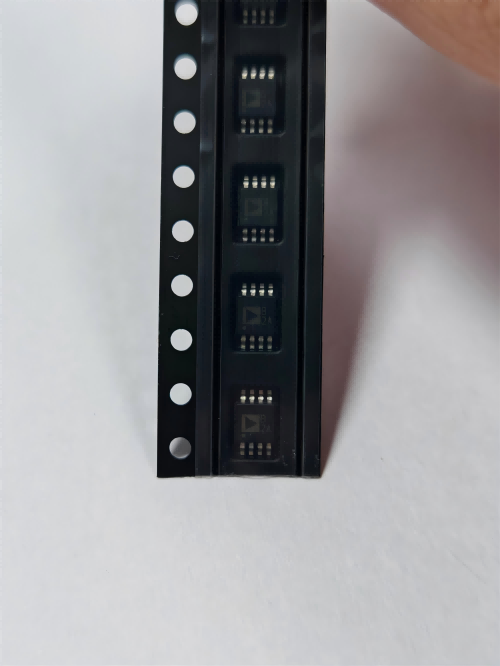

TPS560430YFDBVR
Brand: Texas Instruments
Texas Instruments TPS560430YFDBVR is a power management component designed for AI Servers & Low-Altitude Economy (Drone and UAV) and related applications. In stock at Superb Automation — request a quote for competitive pricing and fast delivery.
Product Specifications
TPS560430YFDBVR
Texas Instruments — Power Management & Signal Chain
Product Overview
The TPS560430YFDBVR from Texas Instruments is a power management / signal chain IC delivering high efficiency, precision regulation, and robust protection. Texas Instruments (TI) is a global leader in analog ICs, power management solutions, and embedded processors.
Superb Automation partners with leading brands including Qorvo, TI, ADI, XILINX, NVIDIA, Intel, ST, MACOM, Renesas, and Coilcraft to provide complete BOM and supply-chain solutions.
Key Features
- High-efficiency power conversion with low quiescent current
- Wide input voltage range with precision output regulation
- Integrated over-current, over-temperature, and short-circuit protection
- Small footprint packaging for space-constrained designs
- AEC-Q100 qualified options available for automotive applications
- Flexible sequencing and soft-start control
Key Specifications
| Input Voltage | V |
| Output Voltage | V |
| Output Current | A |
| Switching Frequency | kHz |
| Efficiency | % |
| Quiescent Current | µA |
| Topology | — |
| Package | — |
| Operating Temp | °C |
| Protection | — |
Applications
Industrial Automation
Automotive Electronics
Telecom Infrastructure
Server & Data Center Power
Medical Devices
Consumer Electronics
Request Quote — In Stock, 100% New & Original, Full Warranty
TPS560430YFDBVR: 600 mA wide input step down converter in a six pin SOT-23 body
TPS560430YFDBVR is a 600 mA synchronous buck that runs from a 4 V to 36 V rail in a six pin SOT-23 body in a SOT-23 body of 6 pins. The input range is 4 V to 36 V, the output current is 600 mA, and the switching frequency is 2.1 MHz on this member, which keeps the inductor and the output capacitor small. The reference is trimmed to plus or minus 1.5 per cent over temperature, the shutdown current is 1 uA, and the body is a six pin SOT-23 measuring 2.90 mm by 1.60 mm.
Order code and package
| TPS560430YFDBVR | 6-pin SOT-23 (DBV), 3000-piece large reel, 2.1 MHz forced PWM member |
| TPS560430YFDBVT | 6-pin SOT-23 (DBV), 250-piece small reel, same silicon |
| TPS560430YFDBVRG4 | 6-pin SOT-23 (DBV), 3000-piece large reel, green row |
| Temperature range | -40 C to 125 C |
| Body size | 2.90 mm by 1.60 mm, six pins, no exposed pad |
Electrical parameters that decide the application
| Input voltage range | 4 V to 36 V |
| Continuous output current | 600 mA |
| Switching frequency | 2.1 MHz on the Y and YF members, 0.935 to 1.265 MHz on the 1.1 MHz members |
| Voltage reference tolerance | plus or minus 1.5 per cent over temperature |
| Shutdown current | 1 uA |
| Light load behaviour | PFM on the Y member, forced PWM on the YF member |
| Output voltage | adjustable by divider on the YF member, fixed 3.3 V on the X3F member |
| Protection | cycle by cycle current limit with hiccup mode on a short |
| Operating junction temperature | -40 C to 125 C |
The five orderable variants and what separates them
| TPS560430XF | 1.1 MHz, forced PWM, adjustable output |
| TPS560430X3F | 1.1 MHz, forced PWM, fixed 3.3 V output |
| TPS560430X | 1.1 MHz, PFM at light load, adjustable output |
| TPS560430Y | 2.1 MHz, PFM at light load, adjustable output |
| TPS560430YF | 2.1 MHz, forced PWM, adjustable output, the member on this page |
| All five | the same six pin body, so a board can trade frequency and light load mode without a change |
Points to check before this part goes on a BOM
The 2.1 MHz switching frequency on this member is the reason the solution fits a 2.90 mm by 1.60 mm body and a small inductor. At that frequency the inductor can be 4.7 uH to 10 uH and the output capacitor a few microfarads, which is what a sensor module or a metering board needs when the converter sits next to the load.
This member is forced PWM, which means it keeps switching at light load instead of skipping cycles. The output ripple stays constant and predictable, the loop stays in the same mode across the load range, and the price is a higher no load current than the PFM member. A radio or an ADC that cannot tolerate a variable ripple spectrum wants this version.
The input range of 4 V to 36 V covers a 12 V and a 24 V industrial bus with margin, and it also covers the aftermarket automotive case where the rail is not a clean 12 V. It does not cover load dump, so a rail that can spike past 36 V needs a clamp ahead of the part.
The reference is trimmed to plus or minus 1.5 per cent over temperature, which is tight enough for a 5 V or 3.3 V rail that feeds a microcontroller without a second regulator. The divider tolerance adds to that, so a 1 per cent resistor pair keeps the total inside 2.5 per cent, and a 5 per cent pair gives away most of the part's advantage.
The output current is 600 mA, and the six pin SOT-23 body has no exposed pad. At 24 V in and 5 V out the conduction loss is small but the switching loss is not, and the junction rise in that body is the limiting factor long before the current limit is reached. A board that needs 600 mA continuously at 24 V in should check the junction temperature on the bench.
Hiccup mode on a short means the part stops, waits, and tries again rather than holding the current limit indefinitely. That is the right behaviour for a rail that feeds a connector, and it also means a shorted load produces a pulsed input current which the upstream supply has to tolerate.
The shutdown current is 1 uA, so the enable pin is a genuine off switch for a battery backed product. The enable threshold on this family is compatible with 3.3 V logic, and the pin can also be driven from a divider on the input rail for a simple under voltage lockout.
PFM and forced PWM on the same footprint is the useful part of this family. A metering board that idles most of the time wants the PFM member for the light load efficiency, and the same board with a radio that transmits in bursts may want the forced PWM member for a constant ripple spectrum. Both are the same six pin body, so the choice can be made late.
The 2.1 MHz frequency also moves the switching energy above the AM band, which simplifies the input filter on a product that has an AM receiver nearby. The trade is a higher switching loss per cycle, which is why the 1.1 MHz members exist for the higher current or higher input voltage cases.
The addendum lists this order code on the DBV body together with a G4 variant and a small reel variant, and the quantity column in the vendor table is split across rows. A purchase order should name the full order code and the reel size, and incoming inspection should read the pack label rather than infer the quantity from the row.
The enable pin is a real logic input with a threshold compatible with the 3.3 V rail that the converter usually feeds, and it can also be driven from a divider across the input for a simple under voltage lockout, so the rail does not try to start while the bus is still rising. The divider draws current from the bus at all times, and its value should be large enough that it does not defeat the 1 uA shutdown figure it is there to protect.
Where this order code fits
It makes a 3.3 V or 5 V rail from a 12 V or 24 V industrial bus in a metering board, a PLC module, a motor drive control card or an aftermarket automotive camera, where the converter has to fit next to the load and run from a rail that is not clean. Teams comparing it with a neighbouring part start from our Power Management Cross Reference page, and teams replacing a part that has gone end of life start from the Pin to Pin Cross Reference page.
Questions buyers ask
Why choose the 2.1 MHz member over the 1.1 MHz one? Because the inductor and the output capacitor become small enough for a compact module, and the switching energy moves above the AM band. The 1.1 MHz members are the better choice when efficiency and thermal margin matter more than size.
What is the difference between Y and YF? Light load behaviour. The Y member drops into PFM and skips cycles at light load for efficiency, while the YF member stays in forced PWM and keeps a constant ripple spectrum at the cost of a higher no load current.
Can it supply 600 mA at 24 V in and 5 V out? The current rating allows it, but the six pin SOT-23 body has no exposed pad, so the junction temperature is the limiting factor. That combination should be measured in the actual enclosure rather than assumed from the current rating.
SUPERB holds and sources this line for production and repair demand, quoted against the exact ordering string with date codes, packing and country of origin stated on the offer. When a part is moving, the Strategic Sourcing page sets out the checks that keep a substitute from failing on the bench.