
TPS3421EGDRYR
Brand: Texas Instruments
Texas Instruments TPS3421EGDRYR is a power management component designed for AI Servers & Low-Altitude Economy (Drone and UAV) and related applications. In stock at Superb Automation — request a quote for competitive pricing and fast delivery.
Product Specifications
TPS3421EGDRYR
Texas Instruments — Power Management & Signal Chain
Product Overview
The TPS3421EGDRYR from Texas Instruments is a power management / signal chain IC delivering high efficiency, precision regulation, and robust protection. Texas Instruments (TI) is a global leader in analog ICs, power management solutions, and embedded processors.
Superb Automation partners with leading brands including Qorvo, TI, ADI, XILINX, NVIDIA, Intel, ST, MACOM, Renesas, and Coilcraft to provide complete BOM and supply-chain solutions.
Key Features
- High-efficiency power conversion with low quiescent current
- Wide input voltage range with precision output regulation
- Integrated over-current, over-temperature, and short-circuit protection
- Small footprint packaging for space-constrained designs
- AEC-Q100 qualified options available for automotive applications
- Flexible sequencing and soft-start control
Key Specifications
| Input Voltage | V |
| Output Voltage | V |
| Output Current | A |
| Switching Frequency | kHz |
| Efficiency | % |
| Quiescent Current | µA |
| Topology | — |
| Package | — |
| Operating Temp | °C |
| Protection | — |
Applications
Industrial Automation
Automotive Electronics
Telecom Infrastructure
Server & Data Center Power
Medical Devices
Consumer Electronics
Request Quote — In Stock, 100% New & Original, Full Warranty
TPS3421EGDRYR: push button controller with two inputs and a factory set timing option for handheld products
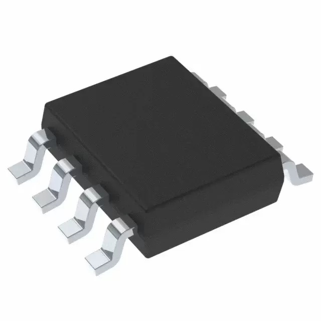
TPS3421EGDRYR is a push button reset controller with two inputs, a factory set timing option and one open drain reset output in a USON body of 6 pins. It works from 1.6 V to 6.5 V, draws 250 nA of supply current, and asserts a reset when both button inputs stay low for the selected delay. The delay is chosen by the TS pin between 7.5 s and 0 s, the reset output stays low for a fixed 400 ms after the button is released, and the body is a 1.45 mm by 1.00 mm SON.
Order code and package
| TPS3421EGDRYR | 6-pin USON (DRY), 1.45 mm by 1.00 mm, 5000 piece large reel, NIPDAU finish |
| TPS3421EGDRYT | same body, 250 piece small reel |
| TPS3421ECDRYR | same body, the other factory timing option of the same silicon |
| TPS3420DDRYR | two inputs, reset released when either input goes high, no fixed pulse |
| TPS3422EGDRYR | single input, reset pulse of 400 ms after the button is released |
| Moisture level | Level 1, 260 C, unlimited floor life |
Electrical parameters that decide the application
| Supply voltage range | 1.6 V to 6.5 V |
| Supply current | 250 nA typical, no load, no button pressed |
| Push button timer, TS tied to ground | 6 s minimum, 7.5 s typical, 9 s maximum |
| Push button timer, TS tied to high | 0 s, the reset follows the button |
| Reset pulse width | 400 ms typical after release |
| Reset output | open drain, active low, able to wire OR with other open drain parts |
| Input thresholds | CMOS compatible, inputs are monitored continuously |
| Operating junction temperature | -40 C to 125 C |
| Package | 6-pin SON, 1.45 mm by 1.00 mm, 0.5 mm pitch |
How the family members differ
| TPS3420 | two inputs, the reset stays low until one input is released, no fixed pulse |
| TPS3421 | two inputs, both have to be low for the delay, then a fixed 400 ms pulse, the row on this page |
| TPS3422 | one input, a fixed 400 ms pulse, for products with a single button |
| Timing suffix E | the factory programmed timing pair applied to the TS pin |
| TS pin | tied low or tied high, and the state is read at power up rather than during operation |
| Output stage | open drain, so the pull up resistor and its rise time belong to the host board |
Points to check before this part goes on a BOM
The two inputs are the point of the part. A product with a power button and a separate reset pinhole can require both to be held before the system is forced off, which is what stops a pocket or a cable from resetting a device that is running. The same hardware then delivers a hard reset only when the user means it, and the firmware does not have to debounce two buttons in software.
The timer is factory set and the TS pin only chooses between the two options programmed into that order code. The 7.5 s option suits a deliberate long press, the 0 s option passes the button straight through. The TS state is read when the part powers up, so changing it while the rail is live does nothing, which is worth knowing on a board where the pin is driven by a controller instead of strapped.
The reset pulse is 400 ms and it starts when the button is released, not when the timer expires. On a product where the user holds the button for ten seconds, the system is held in reset for the whole press plus 400 ms, which is usually what is wanted. A controller that expects a short reset pulse and starts its own power down sequence on the same edge has to allow for the whole press.
The supply current is 250 nA typical, and that number is the reason the part can sit on a battery rail permanently. It is also the number that gets lost when the pull up resistor on the reset line is sized for speed rather than for current. A 10 kOhm pull up to a 3 V rail draws 300 uA when the output is low, which is a thousand times the part's own consumption, so the resistor value is the real standby decision.
The inputs are monitored continuously and there is no clock, so a slow rising edge on the supply does not produce a spurious reset. On a product that is powered from a coin cell that is inserted slowly, that behaviour matters, because a part with an internal oscillator can latch a false state during the ramp. The absence of a clock is also why the supply current stays in the nanoamp range.
The open drain output can be wire ORed with a supply supervisor or a second controller. That is convenient, and it is also the way a product ends up with two devices pulling the same reset line to different rails. The pull up has to go to one rail only, and the lower of the two supply voltages decides the logic high level seen by the processor.
The 1.45 mm by 1.00 mm body has six pins on a 0.5 mm pitch, which is at the limit of what a low cost assembly line can place without a dedicated stencil. A footprint with too much paste on a 0.5 mm pitch part bridges on the first pass, and the fix is the stencil aperture rather than the placement pressure. A line moving this part from a prototype to volume should check the aperture ratio before the first run.
The part has no separate ground reference for the inputs beyond the package ground, so the button wiring shares the return with the processor. On a handheld product with a metal front panel, the button is often connected to the chassis and the chassis to the board ground through a screw. That path is fine for a reset button and it is not fine for an input that carries ESD, so the suppressor belongs at the connector.
The order code carries the timing option after the package letter, so two reels that look identical can behave differently. A build that runs one product with the 7.5 s option and a variant with the 0 s option has to control the two order codes separately, and a substitution during a shortage is the classic way a product ships with a button that resets instantly instead of requiring a long press.
There is no precision reference inside, so the timer is a function of an internal current and capacitor and it is quoted with a range rather than a single value. The 7.5 s option is specified from 6 s to 9 s over temperature and process, which is fine for a human interface and not fine for anything that has to happen at a defined moment. A function with a time requirement belongs in the controller.
The reset output is active low and open drain, so it can hold a processor in reset while the supply is still rising. That is what a product needs when the rail takes tens of milliseconds to come up and the processor would otherwise start on a partial supply. The part itself starts working at 1.6 V, well below the processor minimum, so the reset is asserted before the processor has a chance to run.
A button that is pressed during a battery change produces a reset that the user did not intend. The two input version reduces that risk but does not remove it, and a product that is sensitive to an unintended reset should also gate the input with the presence of the battery. The part does what it is told by its inputs, and there is no logic inside that knows whether the press was deliberate.
Where this order code fits
It sits on the button of a handheld product, a wearable or a battery powered instrument, between the button contacts and the processor reset line, where a press has to be distinguished from a pocket, a cable or a drop. Teams comparing it with a neighbouring part start from our Power Management Cross Reference page, and teams replacing a part that has gone end of life start from the BOM Shortage Recovery page.
Questions buyers ask
How long does the button have to be held? With the TS pin tied low the timer is 7.5 s typical, and both inputs have to stay low for that time. With TS tied high the delay is 0 s and the reset follows the button. The reset output then stays low for a fixed 400 ms after the button is released.
Can the timing be changed in the field? Only within the two options programmed into the order code, and only by changing the TS pin state while the supply is off. A different delay needs a different order code, because the timing is set in the factory rather than by an external component.
Does it work on a coin cell rail? It works from 1.6 V and draws 250 nA, so the part itself is not what drains the cell. The pull up resistor on the reset output and any divider on the button inputs are usually far larger loads than the controller.
Two inputs, one reset, what happens if only one is pressed? Nothing. The part requires both inputs to be low for the selected delay before the reset is asserted, which is what keeps a single accidental press from restarting the product.
SUPERB holds and sources this line for production and repair demand, quoted against the exact ordering string with date codes, packing and country of origin stated on the offer. When a part is moving, the Component Lead Time Solutions page sets out the checks that keep a substitute from failing on the bench.