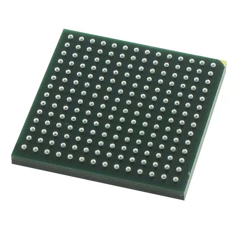

SN65HVD34DR
Brand: Texas Instruments
Texas Instruments SN65HVD34DR is a power management component designed for AI Servers & Low-Altitude Economy (Drone and UAV) and related applications. In stock at Superb Automation — request a quote for competitive pricing and fast delivery.
Product Specifications
SN65HVD34DR
Texas Instruments — Power Management & Signal Chain
Product Overview
The SN65HVD34DR from Texas Instruments is a power management / signal chain IC delivering high efficiency, precision regulation, and robust protection. Texas Instruments (TI) is a global leader in analog ICs, power management solutions, and embedded processors.
Superb Automation partners with leading brands including Qorvo, TI, ADI, XILINX, NVIDIA, Intel, ST, MACOM, Renesas, and Coilcraft to provide complete BOM and supply-chain solutions.
Key Features
- High-efficiency power conversion with low quiescent current
- Wide input voltage range with precision output regulation
- Integrated over-current, over-temperature, and short-circuit protection
- Small footprint packaging for space-constrained designs
- AEC-Q100 qualified options available for automotive applications
- Flexible sequencing and soft-start control
Key Specifications
| Input Voltage | V |
| Output Voltage | V |
| Output Current | A |
| Switching Frequency | kHz |
| Efficiency | % |
| Quiescent Current | µA |
| Topology | — |
| Package | — |
| Operating Temp | °C |
| Protection | — |
Applications
Industrial Automation
Automotive Electronics
Telecom Infrastructure
Server & Data Center Power
Medical Devices
Consumer Electronics
Request Quote — In Stock, 100% New & Original, Full Warranty
SN65HVD34DR: 3.3 V full duplex RS-485 transceiver at 5 Mbps with both enables brought out
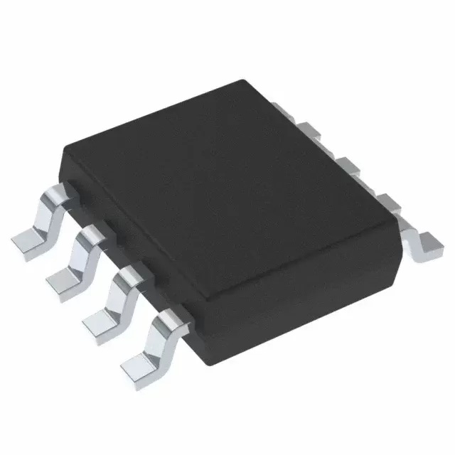
SN65HVD34DR is a differential driver and a differential receiver with separate input and output pins on each, so the two directions occupy four wires and run at the same time in a SOIC body of 14 pins. It runs from a single 3.3 V supply, carries 5 Mbps over cable runs up to 1500 m, presents one eighth of a unit load so 256 nodes fit on one bus, and puts the driver and the receiver on separate pin pairs with an active high driver enable and an active low receiver enable. Disabling both drops the supply current below 1 uA. The differential output is 1.5 V minimum into 54 ohm and the receiver keeps a 50 mV hysteresis across a common mode window from minus 7 V to plus 12 V.
Order code and package
| SN65HVD34DR | SOIC D body, 14 pins, 250 pieces on a small reel, Active in the addendum dated 10 August 2026, NIPDAU finish on the .A row, moisture level 2 with a one year floor life, marking 65HVD34, minus 40 to plus 85 degrees |
| The 250 piece reel | this row is a small reel at 250 pieces and not the 2500 piece large reel the other RS-485 members use. A production order for ten thousand pieces placed against this string is ten reels of 250, and the reel count is what the price is built on |
| SN65HVD34D | the same body in a tube, printed with the same 250 piece quantity and the same moisture level, which is the row a sample order comes from |
| SN65HVD34DRG4.A | printed Obsolete in the current addendum. A bill of materials naming that suffix has no orderable path, and the plain DR row is the live one |
| The rest of the family | SN65HVD30 and SN65HVD31 and SN65HVD32 are the same driver and receiver without enable pins, and SN65HVD33 and SN65HVD35 are the same with them, so the six strings are two functions across three rates |
Electrical parameters that decide the application
| Signalling rate | 5 Mbps on this member, against 1 Mbps on the 35 and 32 and 26 Mbps on the 33 and 30, so the rate is one of three columns and not a suffix |
| Unit load | one eighth of a unit load, which is 256 nodes on one bus, against one half of a unit load and 64 nodes on the 26 Mbps members |
| Duplex | full duplex, which means the driver pair and the receiver pair are separate and both directions run at once, and which also means four wires rather than two |
| Driver differential output | 1.5 V minimum into a 54 ohm load per the RS-485 template and 2 V minimum into 100 ohm per the RS-422 template, both measured with the supply at 3.3 V plus or minus five per cent |
| Common mode output | 1.6 V to 2.3 V steady state, and the change between the two output states is held inside 0.2 V, which is what stops the receiver at the far end from seeing a common mode step on every transition |
| Receiver thresholds | a positive threshold at minus 0.02 V maximum and a negative threshold at minus 0.20 V minimum, with 50 mV of hysteresis between them, which is the margin that absorbs ground noise on a long run |
| Common mode input | minus 7 V to plus 12 V, the window the RS-485 standard asks for, so a ground potential difference between two cabinets sits inside the rating |
| Driver propagation | 25 ns typical, 38 ns typical at the crossing and 65 ns maximum on this member, which is fast enough for 5 Mbps and slow enough not to radiate |
| Standby current | below 1 uA with both the driver and the receiver disabled, which is the number that decides whether a port can stay on a battery backed rail |
| ESD | more than 15 kV human body model on the bus pins, measured to the JEDEC specification |
| Failsafe | a defined output on an idle bus, an open circuit and a shorted pair, so a disabled node or an unplugged cable does not read as a start bit |
| Temperature | minus 40 to plus 85 degrees on the printed rows, with the thermal headroom of the 14 pin body allowing operation higher than that for short periods rather than as a rating |
Family variants and how they differ
| 34 against 33 | same body, same enables, 5 Mbps against 26 Mbps, and 256 nodes against 64. The faster member halves the node count because each input presents more load |
| 34 against 31 | the 31 is the same 5 Mbps and the same 256 nodes without enable pins, which is right for a node that is always listening and always able to talk, and wrong for a bus that has to be quieted |
| 34 against 35 | the 35 is 1 Mbps in the same body with the same enables, and 1 Mbps is what a 1500 m run supports. Choosing by rate alone gets this pair backwards on a long line |
| Against the 5 V family | SN65HVD50 through SN65HVD55 are the same six functions on a 5 V supply, so a mixed 3.3 V and 5 V bus is a matter of quoting the matching member on each board rather than of adding a level shifter |
| Against an isolated part | an ISO3080 class full duplex transceiver adds a barrier for a link that crosses a ground boundary, at four to six times the cost and with a much larger body |
Points to check before this part goes on a BOM
Full duplex is a wiring decision made before the part is chosen. Two pairs, four wires, and the driver of one end permanently connected to the receiver of the other. A customer who orders this part expecting to drop it into a two wire network has a board that cannot work, because the driver pair and the receiver pair are separate pins and there is no internal connection between them. That is worth one sentence in every quote for this family.
The 250 piece reel is the trap in the order code. Every other member of the family is printed at 2500 on a large reel, and this string is 250 on a small one. A buyer who copies the quantity from a neighbouring row orders a tenth of what was intended, and a buyer who assumes the reel price per piece from the 2500 row is quoting a number that does not exist. The reel count belongs in the offer next to the price.
The moisture level on this row is 2 with a one year floor life, against level 1 with no limit on most of the interface parts. That means the parts have to be kept dry and the floor life clock starts when the bag is opened, which is a production constraint rather than a purchasing one, and it is the kind of detail that only surfaces when a line has a reflow problem three months after the parts arrived.
The receiver hysteresis of 50 mV is smaller than the 70 and 80 mV figures on the newer families. On a bus with a large ground difference and slow edges, that 30 mV of extra margin is the difference between a link that works and one that produces a framing error per hour. Where the environment is noisy, the newer member with the larger hysteresis is worth the price, and where the bus is short and quiet this one is entirely adequate.
The 5 Mbps rate and the 256 node count are limits on the same physical quantity. Each node adds capacitance to the bus, and capacitance rounds the edges, and rounded edges at 5 Mbps become intersymbol interference at the far end. A 256 node bus at 5 Mbps is a specification, not a recommendation; the practical node count at that rate over a long run is lower, and the datasheet curves on driver output against load are where that shows up.
The two enables are the reason to choose this member over the 31. An active high driver enable and an active low receiver enable allow a node to listen without driving and allow a multipoint bus to be quieted while a maintenance tool talks. Both disabled is the sub 1 uA state, which is what a battery backed node uses between polls, and the wake path back into the controller is the part of that arrangement the transceiver does not provide.
Where four wires are the right answer
A full duplex link carries a command stream one way and a data stream the other at the same time, which a two wire bus cannot do without turning the line around. Motor drives, weigh scales and process transmitters that stream continuously use this arrangement because the turnaround time of a half duplex link would eat a large fraction of the bandwidth.
The cost is four wires and a driver that is always enabled at one end. A permanently enabled driver on a multipoint bus is a fault waiting to happen, so full duplex networks are normally point to point or a master with a star of slaves, and the topology follows from the part rather than the other way round.
Reading the order code
SN65HVD34 reads as the family, HVD for the transceiver and 34 for the fifth row of the six member table. The D at the end is the 14 pin SOIC and the R is the reel. The rate and the node count are not in the string; they are in the table, and they change with the number. The G4 suffix on the obsolete row is the lead free declaration of a row that is no longer active.
Where this order code fits
Utility meters, DTE and DCE interfaces, industrial process and building automation and point of sale networks are the stated applications, and the common thread is a link that has to carry traffic both ways at once. Teams comparing it with a neighbouring part start from our Pin to Pin Cross Reference page, and teams replacing a part that has gone end of life start from the CAN Bus Transceiver Selection page.
Questions buyers ask
Can it replace a two wire transceiver? No. Full duplex has separate driver and receiver pin pairs, so the board needs four wires and the two halves are not connected inside the package.
How many pieces are on the reel? 250, on a small reel, unlike the neighbouring family members which ship 2500 on a large reel. The reel count changes the order quantity by a factor of ten.
Does it need an external failsafe bias? No. The receiver holds a defined output on an idle bus, an open circuit and a shorted pair.
SUPERB holds and sources this line for production and repair demand, quoted against the exact ordering string with date codes, packing and country of origin stated on the offer. When a part is moving, the How to Verify a Drop in Replacement page sets out the checks that keep a substitute from failing on the bench.