


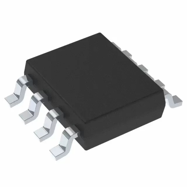

INA819ID
Brand: Texas Instruments
Texas Instruments INA819ID is a power management component designed for Industrial Automation and related applications. In stock at Superb Automation — request a quote for competitive pricing and fast delivery.
Product Specifications
INA819ID
Texas Instruments — Power Management & Signal Chain
Product Overview
The INA819ID from Texas Instruments is a power management / signal chain IC delivering high efficiency, precision regulation, and robust protection. Texas Instruments (TI) is a global leader in analog ICs, power management solutions, and embedded processors.
Superb Automation partners with leading brands including Qorvo, TI, ADI, XILINX, NVIDIA, Intel, ST, MACOM, Renesas, and Coilcraft to provide complete BOM and supply-chain solutions.
Key Features
- High-efficiency power conversion with low quiescent current
- Wide input voltage range with precision output regulation
- Integrated over-current, over-temperature, and short-circuit protection
- Small footprint packaging for space-constrained designs
- AEC-Q100 qualified options available for automotive applications
- Flexible sequencing and soft-start control
Key Specifications
| Input Voltage | V |
| Output Voltage | V |
| Output Current | A |
| Switching Frequency | kHz |
| Efficiency | % |
| Quiescent Current | µA |
| Topology | — |
| Package | — |
| Operating Temp | °C |
| Protection | — |
Applications
Industrial Automation
Automotive Electronics
Telecom Infrastructure
Server & Data Center Power
Medical Devices
Consumer Electronics
Request Quote — In Stock, 100% New & Original, Full Warranty
INA819ID: 35 microvolt instrumentation amplifier with 110 dB supply rejection
INA819ID is a precision instrumentation amplifier with protected inputs and tight supply rejection in a SOIC body of 8 pins. The INA819 shares the low noise input stage of the INA818 line and adds 110 dB of supply rejection at unity gain. Gain is one resistor from 1 to 1000 with the 1 plus 50 kiloohm over RG relation, offset is 10 microvolts typical, and the inputs take 60 volts beyond either rail.
Order code and package
| Order code | INA819ID |
| Function | precision instrumentation amplifier |
| Gain | 1 to 1000, set by one external resistor |
| Gain equation | G equals 1 plus 50 kiloohms divided by RG |
| Package | SOIC, 8 pins |
| Other bodies | 8 pin VSSOP and 8 pin WSON |
| Supply | 4.5 V to 36 V single, plus and minus 2.25 to 18 V |
| Input protection | plus or minus 60 V beyond the rails |
| Noise | 8 nanovolts per root hertz |
| Bandwidth | 2 MHz at gain 1, 270 kHz at gain 100 |
| Datasheet | SBOS903 revision A |
Electrical parameters that decide the application
| Offset voltage | 10 microvolts typical, 35 microvolts maximum |
| Gain drift | 5 ppm per C at gain 1, 35 ppm per C above gain 1 |
| Common mode rejection | 110 dB minimum at gain 10 |
| Power supply rejection | 110 dB minimum, the term that separates this part from its sibling |
| Load stability | 1 nanofarad without a series resistor |
| Temperature range | minus 40 to plus 125 C |
| Output | rail to rail with a reference pin |
| Input stage | protected, with the bias current specified for a bridge source |
| Package thermal | SOIC 8 has enough copper for a 24 V loop transmitter |
| Family position | same input stage as the INA818 with tighter supply rejection |
Points to check before this part goes on a BOM
Supply rejection is the figure that separates this order code from the sibling part. Both hold 10 microvolts of typical offset, and the difference shows up when the rail moves, which on a contactor loaded 24 V bus it does several times an hour.
One hundred and ten dB at unity gain is the case that matters. A preamp running at gain 5 has a smaller input signal and less rejection headroom, so the rail term is larger in proportion even though the datasheet number is higher.
The gain equation uses the 50 kiloohm internal pair, so gain accuracy follows the external resistor. A 0.1 percent resistor at gain 100 gives 0.1 percent gain error, and the drift of that resistor adds to the 35 ppm per C term at the same time.
Sixty volts of protection covers a miswired field cable but not an indefinite short. The input current limit is what keeps the die alive, and a low impedance source still has to be fused or resistor limited.
Eight nanovolts per root hertz at gain 100 is well below what a 16 bit converter can resolve in a 10 kHz band, so the converter and the reference decide the noise floor in that application, not this amplifier.
The 4.5 V minimum supply is the constraint for a 3.3 V board. Where the analogue rail is 3.3 V, the part needs a boosted supply or a substitute from the 1.8 V to 5.5 V current sense line, which carries a narrower common mode range.
Where this order code fits
Boards that share a noisy 24 V rail with contactors or relays are the ones that pay for the extra supply rejection, because the measurement has to survive the rail moving under it. Boards comparing it with a neighbouring part start from our Amplifier Cross Reference page, and boards replacing a part that has gone end of life start from the How to Verify a Drop in Replacement page.
Questions buyers ask
Is this part a drop in replacement for the sibling INA818? The pinout and the gain equation are the same and the packages overlap, so a board can move between them; the change shows up in supply rejection and in the package options offered.
Can it run from a plus and minus 15 V supply? Yes. The dual supply range is plus and minus 2.25 to 18 V, and the inputs take 60 volts beyond those rails without damage.
SUPERB holds and sources this Texas Instruments line for production and repair demand, quoted against the exact ordering string with date codes, packing and country of origin stated on the offer. When a line is moving, the Incoming Inspection Plan page sets out the checks that keep a substitute from failing on the bench.