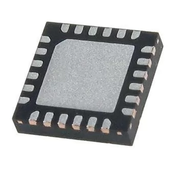
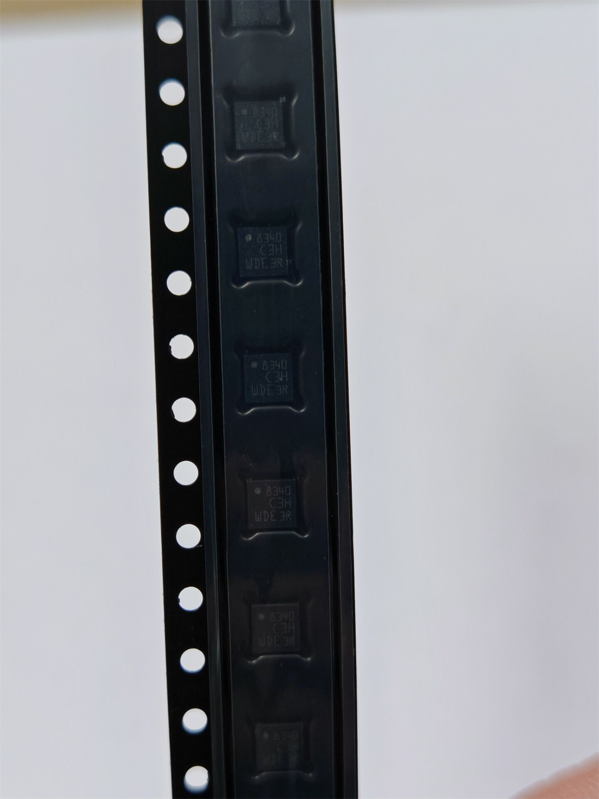
INA241B1IDDFR
Brand: Texas Instruments
Texas Instruments INA241B1IDDFR is a power management component designed for AI Servers & Low-Altitude Economy (Drone and UAV) and related applications. In stock at Superb Automation — request a quote for competitive pricing and fast delivery.
Product Specifications
INA241B1IDDFR
Texas Instruments — Power Management & Signal Chain
Product Overview
The INA241B1IDDFR from Texas Instruments is a power management / signal chain IC delivering high efficiency, precision regulation, and robust protection. Texas Instruments (TI) is a global leader in analog ICs, power management solutions, and embedded processors.
Superb Automation partners with leading brands including Qorvo, TI, ADI, XILINX, NVIDIA, Intel, ST, MACOM, Renesas, and Coilcraft to provide complete BOM and supply-chain solutions.
Key Features
- High-efficiency power conversion with low quiescent current
- Wide input voltage range with precision output regulation
- Integrated over-current, over-temperature, and short-circuit protection
- Small footprint packaging for space-constrained designs
- AEC-Q100 qualified options available for automotive applications
- Flexible sequencing and soft-start control
Key Specifications
| Input Voltage | V |
| Output Voltage | V |
| Output Current | A |
| Switching Frequency | kHz |
| Efficiency | % |
| Quiescent Current | µA |
| Topology | — |
| Package | — |
| Operating Temp | °C |
| Protection | — |
Applications
Industrial Automation
Automotive Electronics
Telecom Infrastructure
Server & Data Center Power
Medical Devices
Consumer Electronics
Request Quote — In Stock, 100% New & Original, Full Warranty
INA241B1IDDFR: the 0.1 percent tier at 10 V/V
The INA241B1IDDFR is the B accuracy tier of the 10 V/V INA241 family in the 8 pin SOT-23-THIN body. It keeps the wide input stage, minus 5 V to 110 V operational, 120 V survival, 166 dB typical DC rejection and 1.1 MHz of bandwidth, and it relaxes the accuracy rows: offset 150 uV maximum with 0.5 uV per degree, gain error 0.1 percent maximum with 5 ppm per degree. That is fifteen times the offset and ten times the gain error of the A tier at the same gain.
The B tier is not a degraded part. It is the same die sorted to a wider window, and for an overcurrent comparator or a load detection threshold the wider window costs nothing, because the decision is a threshold with tens of percent of margin. Where it does cost something is a measurement that has to be trusted without calibration, and that is the line a specification has to draw rather than the price list.
Key data for the INA241B1IDDFR
| Gain | 10 V/V fixed, available in the B tier at 10, 20, 50, 100 and 200 V/V |
| Common mode | Minus 5 V to 110 V operational, minus 20 V to 120 V survival, independent of the supply |
| Accuracy | Offset 150 uV maximum, 0.5 uV per degree of drift, gain error 0.1 percent maximum, gain drift 5 ppm per degree |
| Rejection | 166 dB DC typical, 104 dB at 100 kHz, 89 dB at 1 MHz, with PWM rejection to 125 kHz of switching |
| Speed | 1.1 MHz at all gains, 8 V per microsecond slew, settling to 1 percent in 1 us |
| Supply | 2.7 V to 20 V, 2.5 mA typical and 3 mA maximum, minus 40 C to 125 C |
Body, marking and reel data
| Body | DDF, 8 pin SOT-23-THIN at 2.9 mm by 2.8 mm, the same land pattern as the A tier |
| Reel | 3000 pieces on a large reel at moisture level 1, unlimited floor life |
| Finish | NIPDAU plated leads, compatible with a 260 C lead free profile |
| Marking | The gain and body code, with no visible marker that separates the B tier from the A tier of the same gain |
| Tier difference | Same die, same pinout, wider offset and gain window; nothing in the package or the marking differs |
Where the wider window is enough
Overcurrent protection is the clearest case. A drive that trips at 30 A with a 25 percent margin does not care whether the threshold is off by 150 uV, because 150 uV through a 0.5 milliohm shunt is 0.3 A, one percent of the trip point. The same argument holds for load detection, for a stall detector and for a soft start time-out.
The argument fails for anything reported to a host as a measurement. If an energy meter, a fuel gauge or a torque estimate is built on the reading, the wider window shows up as a bias error that a customer sees in the field and a service engineer cannot reproduce on a bench. The other place it fails is a low current measurement: at 10 V/V, 150 uV of offset is 15 mA through a 10 milliohm shunt, which is the whole standby current of a small module. Where the two tiers are being compared on a real circuit, the amplifier cross reference note carries both rows, and the drop in replacement check note sets out the bench test we run before accepting a tier change on an existing build.
Buyer questions on the INA241B1IDDFR
Is the B tier a lower grade die? The vendor describes a single device with two published accuracy versions, and the packages are identical. The practical meaning is that the offset and gain windows differ, so the two strings are not interchangeable on a specification that depends on those windows.
Does the B tier have the same bandwidth and rejection? Yes. The frequency response and the common mode rejection rows are shared, which is why the B tier is still usable in a fast loop.
Can a board mix A and B tiers on the same board? Only with a host software or test limit change, because the pass and fail limits for a current measurement shift with the tier. Boards that mix them without saying so produce field returns that cannot be explained.
Availability and ordering notes
The DDF rows are active at 3000 pieces on a large reel at moisture level 1, and the A and B tiers share the body, the reel and the marking. Nothing on the part tells the two apart, so the reel label is the only record of which tier a board received. That is why we hold the tiers on separate line items, label them separately at kitting and keep the date code with the shipment on the date code management record. Where a build is qualified on the A tier and a shortage forces the B tier, the change is a documented deviation rather than a silent substitution.