


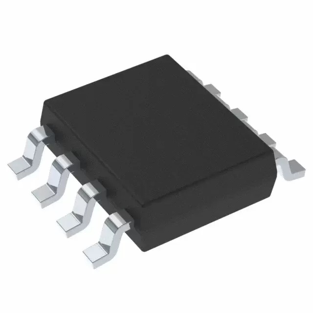

INA2180A1IDGKR
Brand: Texas Instruments
Texas Instruments INA2180A1IDGKR is a power management component designed for Industrial Automation and related applications. In stock at Superb Automation — request a quote for competitive pricing and fast delivery.
Product Specifications
INA2180A1IDGKR
Texas Instruments — Power Management & Signal Chain
Product Overview
The INA2180A1IDGKR from Texas Instruments is a power management / signal chain IC delivering high efficiency, precision regulation, and robust protection. Texas Instruments (TI) is a global leader in analog ICs, power management solutions, and embedded processors.
Superb Automation partners with leading brands including Qorvo, TI, ADI, XILINX, NVIDIA, Intel, ST, MACOM, Renesas, and Coilcraft to provide complete BOM and supply-chain solutions.
Key Features
- High-efficiency power conversion with low quiescent current
- Wide input voltage range with precision output regulation
- Integrated over-current, over-temperature, and short-circuit protection
- Small footprint packaging for space-constrained designs
- AEC-Q100 qualified options available for automotive applications
- Flexible sequencing and soft-start control
Key Specifications
| Input Voltage | V |
| Output Voltage | V |
| Output Current | A |
| Switching Frequency | kHz |
| Efficiency | % |
| Quiescent Current | µA |
| Topology | — |
| Package | — |
| Operating Temp | °C |
| Protection | — |
Applications
Industrial Automation
Automotive Electronics
Telecom Infrastructure
Server & Data Center Power
Medical Devices
Consumer Electronics
Request Quote — In Stock, 100% New & Original, Full Warranty
INA2180A1IDGKR: the dual gain of twenty current sense amplifier on a 2500 piece reel
INA2180A1IDGKR is the dual current sense amplifier with a fixed gain of 20, in the eight pin VSSOP on a 2500 piece large reel. Its inputs accept a common mode from 0.2 volts below ground to 26 volts on a supply of 2.7 to 5.5 volts, so it measures a shunt on a 24 volt rail while running from the logic rail, and both channels draw 355 microamps typical.
The A1 code is the gain of 20 member of a family that also offers 50, 100 and 200, and the reel carries the marking 1CX6, a nickel palladium gold or tin finish depending on the row, and moisture level 2 with a one year floor life. The bandwidth of 350 kilohertz is the highest of the four gains, which is the compensation for the lowest gain.
INA2180A1IDGKR as the vendor document publishes it
| Channels | 2 |
| Gain | 20 V/V, the A1 member of the family |
| Supply | 2.7 to 5.5 volts |
| Common mode range | minus 0.2 to 26 volts |
| Quiescent current | 355 microamps typical, 500 maximum for both channels, 520 over temperature |
| Offset at zero common mode | 25 microvolts typical, 150 maximum |
| Offset over the full range | 100 microvolts typical, 500 maximum |
| Offset drift | 0.2 microvolts per degree typical, 1 maximum |
| Rejection | 84 minimum, 100 typical decibels |
| Power supply rejection | 8 microvolts per volt typical, 40 maximum |
| Gain error | 0.1 typical, 1 maximum per cent |
| Gain drift | 1.5 parts per million per degree typical, 20 maximum |
| Nonlinearity | 0.01 per cent between 0.5 volts and 0.5 volts below the supply |
| Voltage noise | 40 nanovolts per root hertz |
| Bandwidth and slew | 350 kilohertz, 2 volts per microsecond |
| Output swing | within 20 millivolts of the supply, 8 milliamps maximum |
| Temperature range | minus 40 to plus 125 degrees |
| Vendor status | active, 2500 piece large reel |
| Catalogue code | INA2180A1IDGKR |
| Carrier | large reel of 2500 |
| Marking | 1CX6 |
| Moisture level | level 2, 260 degrees, one year floor life |
A gain of twenty, and a common mode that goes above the supply
INA2180A1IDGKR is a dual current sense amplifier with a fixed gain of 20, which is the A1 member of a family that also offers 50, 100 and 200. The inputs accept a common mode from 0.2 volts below ground to 26 volts, on a supply of 2.7 to 5.5 volts, so the part measures a shunt on a 24 volt rail while running from a 3.3 volt logic rail.
That window is the whole point of the family. A current sense amplifier that only works inside its own supply needs a separate higher rail or a level shift, and the 26 volt window removes both. The gain of 20 suits a 10 milliohm shunt at 5 amps, which gives 50 millivolts of signal and 1 volt at the output, and the four gain options let the same board cover a 0.5 amp and a 20 amp channel with one part number.
One hundred and fifty microvolts at zero common mode, five hundred across the range
The offset of INA2180A1IDGKR is 25 microvolts typical and 150 maximum when the common mode sits at zero volts, and 100 typical with 500 maximum over the full zero to 26 volt window at a 10 millivolt sense voltage. The drift is 0.2 microvolts per degree typical and 1 maximum, and the power supply rejection is 8 microvolts per volt typical against 40 maximum.
Read at the shunt, 500 microvolts divided by a gain of 20 is 25 microvolts of input error, and on a 10 milliohm shunt that is 2.5 milliamps of current error. On a 1 milliohm shunt it is 25 milliamps, which is why the family is offered in four gains: the error is set by the sense voltage, so a smaller shunt needs a higher gain rather than a better amplifier. The offset is specified by extrapolation to zero sense voltage, which is the honest way to quote a current sense part.
Eighty four decibels of rejection, measured where the part is used
The common mode rejection of INA2180A1IDGKR is 84 dB minimum and 100 dB typical, and it is specified over the full zero to 26 volt common mode at a 10 millivolt sense voltage across the whole minus 40 to plus 125 degree range rather than at room temperature alone. The gain error is 0.1 per cent typical and 1 per cent maximum, with a gain drift of 1.5 parts per million per degree typical and 20 maximum.
The rejection figure is the one that decides whether the part can sit on a switching node. A 24 volt rail that swings 1 volt at 100 kilohertz puts that volt on both inputs, and 84 dB turns it into 63 microvolts at the input, which is 1.3 millivolts at the output of a gain of 20 stage. The 1 per cent gain error is larger than that on a 1 volt output, so a channel that needs absolute accuracy trims the gain rather than the offset.
Three hundred and fifty kilohertz, and three hundred and fifty five microamps for two channels
The bandwidth of INA2180A1IDGKR is 350 kilohertz, the highest of the four gain options, with a slew rate of 2 volts per microsecond and a nonlinearity of 0.01 per cent between 0.5 volts and 0.5 volts below the supply. The quiescent current is 355 microamps typical and 500 maximum for both channels, rising to 520 microamps maximum over temperature.
Those two rows are why the part is used in a battery product. Two channels of current sense for half a milliamp is a fraction of what a controller with an integrated sense amplifier draws, and 350 kilohertz is enough to follow a motor current through a pulse width modulated cycle at 20 kilohertz with 17 samples per period. The output stage swings to within 20 millivolts of the supply and to within 0.5 millivolts of ground into 10 kilo-ohms.
The carrier rows, and the one code that is no longer produced
The dual channel part in the eight pin VSSOP is published on a 2500 piece large reel as INA2180A1IDGKR, with the marking 1CX6, a nickel palladium gold finish, moisture level 2 at 260 degrees with a one year floor life, and a temperature range of minus 40 to plus 125 degrees. The small reel code INA2180A1IDGKT is printed as obsolete in the same addendum, with no quantity and no finish.
That is a catalogue issue rather than a technical one. A buyer who needs 250 pieces has to take a partial reel of the R code or find stock, because the T code is no longer produced. The single channel and four channel members of the family are unaffected, and the electrical rows are identical across the three, so a board that has to change channel count keeps its calibration.
Where a gain of twenty current sense belongs
INA2180A1IDGKR belongs on a 12 or 24 volt rail with a 10 milliohm shunt and a 5 amp load, in a battery charger, a motor drive, a hot swap card, a power over ethernet port and a server supply. The 26 volt common mode, the 350 kilohertz bandwidth and the 355 microamps are the three rows that fit those cases, and the dual channel covers a positive and a negative rail in one package.
It does not belong on a rail above 26 volts, where the input window ends even though the part would survive. It does not belong on a shunt below 1 milliohm without accepting milliamps of error, because the offset is fixed and the gain is fixed. It does not belong in a bidirectional measurement that needs a signed output, because the output is unipolar. Our amplifier cross reference page covers the four gain options, and the BOM scrubbing page covers the shunt and the gain against the bill of materials.
The shunt and the gain are chosen together, because the offset error is set by the sense voltage. Our amplifier cross reference page covers the four gain options, and the BOM scrubbing page covers the shunt against the bill of materials.
Is 350 kilohertz enough for a motor drive? At 20 kilohertz of switching it is 17 samples per period, which is enough to reconstruct the current envelope but not the ripple.
What is the error on a 10 milliohm shunt? 500 microvolts of offset over the range divided by the gain is 25 microvolts at the input, which is 2.5 milliamps.