


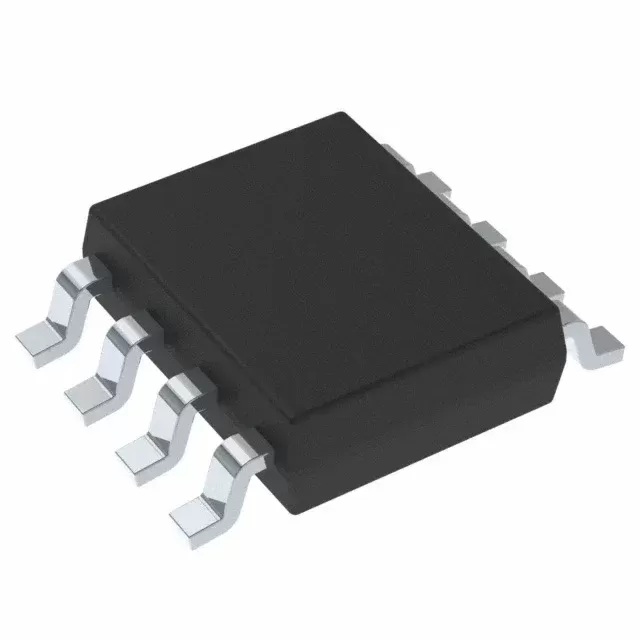

DRV8874QPWPRQ1
Brand: Texas Instruments
Texas Instruments DRV8874QPWPRQ1 is a power management component designed for Industrial Automation and related applications. In stock at Superb Automation — request a quote for competitive pricing and fast delivery.
Product Specifications
DRV8874QPWPRQ1
Texas Instruments — Power Management & Signal Chain
Product Overview
The DRV8874QPWPRQ1 from Texas Instruments is a power management / signal chain IC delivering high efficiency, precision regulation, and robust protection. Texas Instruments (TI) is a global leader in analog ICs, power management solutions, and embedded processors.
Superb Automation partners with leading brands including Qorvo, TI, ADI, XILINX, NVIDIA, Intel, ST, MACOM, Renesas, and Coilcraft to provide complete BOM and supply-chain solutions.
Key Features
- High-efficiency power conversion with low quiescent current
- Wide input voltage range with precision output regulation
- Integrated over-current, over-temperature, and short-circuit protection
- Small footprint packaging for space-constrained designs
- AEC-Q100 qualified options available for automotive applications
- Flexible sequencing and soft-start control
Key Specifications
| Input Voltage | V |
| Output Voltage | V |
| Output Current | A |
| Switching Frequency | kHz |
| Efficiency | % |
| Quiescent Current | µA |
| Topology | — |
| Package | — |
| Operating Temp | °C |
| Protection | — |
Applications
Industrial Automation
Automotive Electronics
Telecom Infrastructure
Server & Data Center Power
Medical Devices
Consumer Electronics
Request Quote — In Stock, 100% New & Original, Full Warranty
DRV8874QPWPRQ1: 200 mΩ of H bridge with current sense on the die
The DRV8874QPWPRQ1 is the low resistance member of the DRV887x automotive family, published ACTIVE with a 3000 piece reel. Both FETs together measure 200 mΩ, so the same 6 A peak current that would cook an eight pin body leaves this sixteen pin HTSSOP comfortable. The part also carries an internal current mirror that reports a scaled copy of the motor current on the IPROPI pin, which removes the power shunt from the board and, more importantly, removes the thermal drift that a shunt brings with it.
Three features are worth reading past the headline. The charge pump keeps both high side FETs enhanced so the bridge can run at 100 per cent duty cycle without a bootstrap refresh gap. The PMODE pin is tri level and selects phase and enable control, pure PWM control, or independent half bridge control, which means one part number covers three different controller interfaces. The IMODE pin is quad level and selects whether an overcurrent event retries automatically or latches the outputs off, and that choice is made in hardware rather than in code.
The DRV8874QPWPRQ1 rows as the addendum publishes them
| Part class | Automotive brushed DC motor driver with integrated current sense |
| Vendor status | ACTIVE, production data |
| Data sheet | SLVSF67B, August 2019, revised January 2021 |
| Qualification | AEC-Q100 grade 1, functional safety capable |
| Operating voltage | 4.5 V to 37 V |
| Peak output current | 6 A |
| RDS(on), each FET, 25 degrees | 100 mΩ typical, 120 mΩ maximum at 13.5 V and 2 A |
| RDS(on), each FET, 150 degrees | 160 mΩ typical, 190 mΩ maximum |
| Current mirror ratio | 450 µA per amp of load current |
| Mirror accuracy, 2 to 4 A | 5.5 per cent |
| Mirror accuracy, 1 to 2 A | 6 per cent |
| Mirror accuracy, below 0.4 A | 30 mA offset, not a percentage |
| Current regulation off time | 25 µs |
| Sense delay | 6 µs, deglitch 1.7 µs, blanking 2.7 µs |
| Propagation delay | 1.75 µs |
| Output dead time | 750 ns |
| Output rise and fall | 500 ns each |
| Undervoltage lockout | 4.3 to 4.6 V rising, 4.2 to 4.5 V falling |
| Overcurrent trip | 6 A minimum, 10 A maximum |
| Thermal shutdown | 160 to 175 to 190 degrees, 20 degrees hysteresis |
| Sleep current | Under 1 µA at 24 V and 25 degrees junction |
| Body | HTSSOP with PowerPAD, 16 pins, 5.00 by 4.40 millimetres |
| Reel row | DRV8874QPWPRQ1, 3000 pieces, large tape and reel, Active |
| Marking | 8874Q |
| Moisture level | Level 3 at 260 degrees, 168 hours floor life |
The mirror accuracy rows are the ones a controls engineer reads first. Below 0.4 A the error is expressed as a fixed 30 mA offset rather than a percentage, because the mirror cannot resolve small currents against its own offset. That single row decides whether this part can be used to detect a light load such as a mirror fold motor reaching its stop, or only to detect a stall at several amps.
Reading the resistance numbers against a duty cycle
200 mΩ total at 25 degrees becomes 320 mΩ at 150 degrees, and the two numbers bracket the whole operating window. At 3 A continuous the conduction loss is 1.8 W at the cold figure and 2.9 W at the hot one, which is why the exposed pad and the copper under it are part of the specification rather than a preference. The sixteen pin body spreads the pad over a larger area than the eight pin part, so the same copper pour yields a lower junction temperature, and that is the practical reason to choose this row over the smaller one when average current exceeds 2 A.
The 750 ns dead time is longer than the 220 ns of the eight pin family, and the difference is deliberate: the larger FETs need more time to avoid shoot through. For a controller running at 20 kHz that is irrelevant. For a controller that chops at 40 kHz the dead time starts to eat into the effective duty cycle at low speed, and the resulting non linearity shows up as a motor that will not run smoothly below 10 per cent throttle.
The three control modes and what they cost in pins
In phase and enable mode the bridge takes a direction pin and a PWM pin, which is the interface most microcontrollers already have. In PWM mode both inputs switch together and the bridge behaves as a full bridge driven from one signal. In independent half bridge mode the two outputs can be driven separately, which is how the part drives two unidirectional loads such as a pair of solenoids, and also how it produces a bi level drive for a piezo actuator.
Each mode uses the same three pins, and the mode is set by a resistor divider on PMODE at power up. That means the configuration is frozen in hardware and cannot be changed by software, which is good for functional safety reviews and awkward for a platform that wants one board to serve two mechanisms. In practice a zero ohm link in the divider is the workaround, and it has to be placed where a production test can read the resulting mode.
Thermal and board questions
The thermal pad is 3.55 by 2.46 millimetres on the HTSSOP body, and the vendor's stencil guidance suggests a paste opening slightly larger than the pad with a thickness of 0.125 millimetres. Voids under a pad that size are the usual cause of a driver that runs twenty degrees hotter than the calculation predicts, so the paste deposit and the reflow profile matter more than the copper area beyond a certain point.
The current sense pin needs a resistor to ground and a small filter capacitor. Because the mirror output is a current, the resistor value sets the full scale voltage, and the filter sets how fast a stall can be detected. A 1 k resistor with 1 nF gives a 1 µs time constant, which is fast enough for stall detection and slow enough to reject switching noise; a 10 k resistor doubles the signal but also the noise pickup on the trace.
Buying DRV8874QPWPRQ1
The reel carries 3000 pieces, which is larger than the 2500 of the eight pin family and reflects the higher average consumption of a body controller. There is no tube row and no tray row, so an engineering build buys a full reel or a broken one. For the automotive programme the level 3 window is the constraint, and a broken reel needs a bake record before it can be used in a qualified build.
Where a customer needs the same function at lower current, the DRV8876-Q1 is pin to pin with 700 mΩ and 3.5 A, which is the reason the family was built as a set of resistance options in one footprint. Choosing between them is a thermal question, not an interface question, and the answer is usually found by computing dissipation at the stall current rather than at the rated current.
Questions that arrive with this part number
The first is whether the integrated sense can replace an external shunt in a safety function. It can replace the measurement, but the mirror is not a calibrated metrology channel: the accuracy is 5.5 per cent at high current and an offset below 0.4 A, so a protection threshold has to be set with that tolerance in mind. The second is whether the latch mode is sticky across a power cycle. It is not, because a power cycle resets the device, so a latched fault has to be recorded by the controller if the record has to survive an ignition cycle.
The third is the behaviour at 4.5 V. The undervoltage lockout sits at 4.3 to 4.6 V, so a 5 V rail that sags during a cold crank start can put the part in and out of lockout, and the outputs will chatter. A supply that holds 5.5 V through the crank is the requirement, not 4.5 V.
For a build that mixes this row with the lower current member of the family, the pin to pin page lists both, and the lead time page covers the reel position for the automotive grade.