


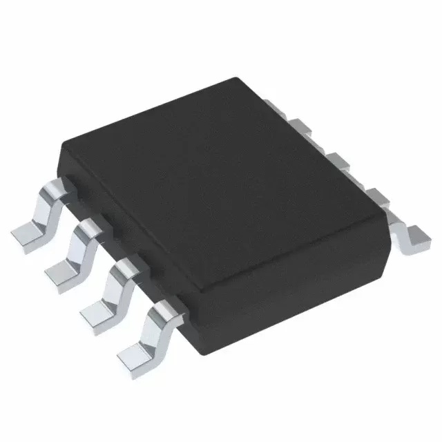

CD4017BCM
Brand: Texas Instruments
Texas Instruments CD4017BCM is a power management component designed for Industrial Automation and related applications. In stock at Superb Automation — request a quote for competitive pricing and fast delivery.
Product Specifications
CD4017BCM
Texas Instruments — Power Management & Signal Chain
Product Overview
The CD4017BCM from Texas Instruments is a power management / signal chain IC delivering high efficiency, precision regulation, and robust protection. Texas Instruments (TI) is a global leader in analog ICs, power management solutions, and embedded processors.
Superb Automation partners with leading brands including Qorvo, TI, ADI, XILINX, NVIDIA, Intel, ST, MACOM, Renesas, and Coilcraft to provide complete BOM and supply-chain solutions.
Key Features
- High-efficiency power conversion with low quiescent current
- Wide input voltage range with precision output regulation
- Integrated over-current, over-temperature, and short-circuit protection
- Small footprint packaging for space-constrained designs
- AEC-Q100 qualified options available for automotive applications
- Flexible sequencing and soft-start control
Key Specifications
| Input Voltage | V |
| Output Voltage | V |
| Output Current | A |
| Switching Frequency | kHz |
| Efficiency | % |
| Quiescent Current | µA |
| Topology | — |
| Package | — |
| Operating Temp | °C |
| Protection | — |
Applications
Industrial Automation
Automotive Electronics
Telecom Infrastructure
Server & Data Center Power
Medical Devices
Consumer Electronics
Request Quote — In Stock, 100% New & Original, Full Warranty
CD4017BCM: a decade counter whose catalogue suffix the vendor does not list
CD4017BCM is a CD4017B decade counter in the small outline body, and this page has to start with a procurement fact rather than an electrical one: the vendor package addendum for the CD4017B family does not print a CM suffix at all. The rows it does print for the 16-lead small outline body are CD4017BM, listed as Obsolete with a blank quantity, and CD4017BM96 and CD4017BM96.A, both Active at 2500 pieces on a large reel. The CM string therefore has no published packing, no published status and no published marking, which means a purchase order written against it cannot be matched to a vendor row without a confirmation.
The function itself is well defined. The vendor descriptor reads CMOS Decade Counter with 10 Decoded Outputs, the document is the CD4017B and CD4022B data sheet revision C, and the parametric table gives a 10 MHz typical counting rate at 10 V, balanced outputs, positive input clamp diodes, a standard speed classification above 50 ns, and a minus 55 to plus 125 degree range. The part is a five stage Johnson counter with ten decoded outputs, a clock input with Schmitt trigger shaping, a clock inhibit input, a reset input and a carry out.
The CD4017BCM row against what the addendum prints
| Part class | Decade counter, five stage Johnson, ten decoded outputs |
| Vendor descriptor | CMOS Decade Counter with 10 Decoded Outputs |
| Vendor document | CD4017B and CD4022B data sheet revision C |
| Counting rate, vendor feature line | 10 MHz typical at 10 V |
| Inputs | Clock, clock inhibit, reset |
| Clock input shaping | Schmitt trigger action, unlimited rise and fall time |
| Outputs | Ten decoded outputs, active high for one clock period each |
| Carry out | One pulse per ten clock cycles, for ripple chaining |
| Supply range | 3 V to 18 V |
| Output type | Push pull, balanced outputs |
| Input type | Standard CMOS |
| Package implied by the suffix | Small outline, 16 leads |
| CM suffix in the addendum | Not printed for this family |
| SOIC rows the addendum does print | CD4017BM Obsolete, CD4017BM96 and CD4017BM96.A Active at 2500 pieces |
| PDIP row the addendum prints | CD4017BE, Active, 25 piece tube |
| SOP row | CD4017BNSR, 2000 piece reel |
| TSSOP rows | CD4017BPW Obsolete, CD4017BPWR Active at 2000 pieces |
| Ceramic rows | CD4017BF and CD4017BF3A, 25 piece tube, tin lead finish |
| Marking for the active rail body rows | CD4017B and CM017B on the TSSOP row |
| Operating range on all printed rows | Minus 55 to plus 125 degrees |
How the counter behaves, and why the Schmitt clock matters
The counter advances one count on each positive clock transition while the clock inhibit input is low, and the ten decoded outputs go high one at a time for a full clock period. The reset input clears the count to zero asynchronously, and the carry out produces one pulse every ten clock cycles so that several packages can be chained into a longer count without external logic. Anti-lock gating inside the part keeps the sequence from stalling in an unused state, which is the failure that a counter built from separate flip-flops is prone to.
The Schmitt trigger on the clock input is the detail that makes the part usable with slow signals. A mechanical switch, an RC oscillator built from a 4069 inverter, or a long cable with a slow edge all produce transitions that a plain CMOS input would see as a burst of edges. The Schmitt input converts a slow ramp into a single transition, which means the counter advances once per event rather than once per bounce, and the vendor states that the clock input allows unlimited rise and fall times.
Ten outputs, one of them at a time: the circuits this part is used in
The first use is a sequence generator. Ten outputs going high in turn drive ten LEDs, ten relays or ten steps of a state machine, with the reset input setting the start point and the inhibit input freezing the sequence. The second is division by ten, with the carry out feeding the next counter and the decoded outputs either used or ignored. The third is a one-of-ten selector in a test fixture, where the decoded output drives an analogue switch and the counter steps through channels under a clock from the test controller.
What the part cannot do is drive a load directly. The decoded outputs are logic outputs with a few milliamps of drive, so an LED needs a series resistor and a relay needs a transistor. A load that draws more than the output can supply pulls the output level down and, in the worst case, disturbs the counter itself, because the output stage and the internal logic share a supply pin.
The CM suffix problem, and how to close it
A catalogue string that the vendor does not print is not necessarily wrong, because suffixes do exist in distributor and internal numbering schemes. It is, however, unverifiable until a document confirms it, and the risk on an obsolete prone family is that a broker supplies an old Harris or RCA part with a CM marking against an order for a current TI row. The practical route is to ask for the vendor confirmation in writing, or to switch the purchase order to the active CD4017BM96 string, which is the same die in the same body and carries a published 2500 piece reel, or to the CD4017BE if a through-hole part suits the board.
The substitution between those rows is electrical rather than functional: the die, the counting rate and the temperature range are identical, and only the body and the packing change. That makes the CM question a paperwork problem with a clean answer, which is the cheapest kind to have on an obsolete prone part.
Where the 4017 sits against the 4022 and the 4026
The CD4022B is the same die with four stages instead of five, giving eight decoded outputs and a carry out every eight clocks, and it appears in the same document. The CD4026B adds a seven segment decoder to a five stage counter, so it drives a display directly instead of giving ten separate outputs, and the CD4029B is a presettable up and down counter with a binary or a BCD mode. A board that needs a decimal readout takes the 4026B, a board that needs ten discrete steps takes the 4017B, and a board that needs to count up and down takes the 4029B.
Against a modern microcontroller the 4017 still holds a place in circuits that have no program to run: a test jig, a lamp sequencer, a divide by ten stage in front of an older counter. It costs one package, no code and no clock source of its own, which is why it stays in catalogues that have dropped far more capable parts.
Incoming checks before a CM order is placed
The first check is documentary and has to come before the goods: a written confirmation of the suffix from the vendor or the supplier, including the body, the packing quantity and the marking. The second is the function test, which for this part is a clock, a reset and a check that each of the ten outputs goes high once per cycle with no two outputs high at the same time. The third is the carry out, which is the output most often left untested and the one that matters when the part is chained.
The reference pages are the obsolete part cross reference hub for the replacement route, incoming inspection plan for the test sequence, and the sourcing audit trail page when a suffix has to be justified to an auditor.
Questions that come up on this part
Whether the counter can be stopped without losing the count. It can, by holding the clock inhibit input high, which stops the count and keeps the current output active.
Whether two counters can be chained for a count of one hundred. They can, with the carry out of the first feeding the clock of the second, and the reset of both tied to the same line for a common clear.
Whether the decoded outputs can drive a seven segment display. They cannot, because the outputs are one of ten rather than a segment pattern, and a display needs the 4026B or a decoder.
Whether the CM code is a real part. It may be, but the vendor addendum for this family does not print it, so the answer has to come from a written confirmation rather than from a catalogue.