


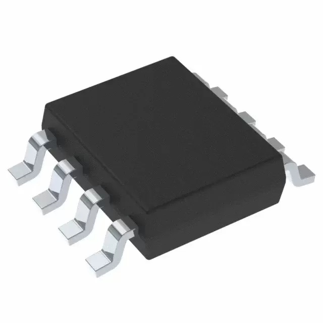

BQ7692003PWR
Brand: Texas Instruments
Texas Instruments BQ7692003PWR is a power management component designed for Industrial Automation and related applications. In stock at Superb Automation — request a quote for competitive pricing and fast delivery.
Product Specifications
BQ7692003PWR
Texas Instruments — Power Management & Signal Chain
Product Overview
The BQ7692003PWR from Texas Instruments is a power management / signal chain IC delivering high efficiency, precision regulation, and robust protection. Texas Instruments (TI) is a global leader in analog ICs, power management solutions, and embedded processors.
Superb Automation partners with leading brands including Qorvo, TI, ADI, XILINX, NVIDIA, Intel, ST, MACOM, Renesas, and Coilcraft to provide complete BOM and supply-chain solutions.
Key Features
- High-efficiency power conversion with low quiescent current
- Wide input voltage range with precision output regulation
- Integrated over-current, over-temperature, and short-circuit protection
- Small footprint packaging for space-constrained designs
- AEC-Q100 qualified options available for automotive applications
- Flexible sequencing and soft-start control
Key Specifications
| Input Voltage | V |
| Output Voltage | V |
| Output Current | A |
| Switching Frequency | kHz |
| Efficiency | % |
| Quiescent Current | µA |
| Topology | — |
| Package | — |
| Operating Temp | °C |
| Protection | — |
Applications
Industrial Automation
Automotive Electronics
Telecom Infrastructure
Server & Data Center Power
Medical Devices
Consumer Electronics
Request Quote — In Stock, 100% New & Original, Full Warranty
BQ7692003PWR: battery pack analogue front end for three to five series cells
BQ7692003PWR is the measurement and protection front end that a pack controller sits on top of in a TSSOP body of 20 pins. The part monitors three to five series cells, drives low-side charge and discharge field effect transistors, balances cells with integrated switches and reports over I2C. A 2.5 V or 3.3 V regulator feeds the host, and the device tolerates cells being connected in random order. It is an analogue front end, so the protection decision and the state of charge estimation both live in the host firmware.
Order code and package
| Order code | BQ7692003PWR |
| Function | pack analogue front end, 3 to 5 series cells, 18 V typical pack |
| Cell balancing | integrated balancing switches, external resistors |
| FET drive | low-side N-channel charge and discharge drivers |
| Regulator | 2.5 V or 3.3 V, factory set |
| Interface | I2C with optional CRC |
| Address | factory set in EEPROM and not changeable |
| Package | TSSOP, 20 pins, 6.50 mm by 4.40 mm |
| Temperature range | minus 40 to plus 85 C |
| Coulomb counter | external sense resistor on SRP and SRN |
| Datasheet | SLUSBK2 revision I |
| Family | 10-cell and 15-cell members share the register set |
Electrical parameters that decide the application
| Cell count | 5 series maximum on this code, 10 on the BQ76930 and 15 on the BQ76940 |
| Pack voltage | 18 V typical, so a 6-cell pack belongs on the larger member |
| Regulator | 2.5 V or 3.3 V, fixed in EEPROM at the factory |
| I2C address | fixed in EEPROM, so two packs on one bus need two different order codes |
| Balancing | internal switches only, the current is set by the external resistor and the cell voltage |
| Protection | the comparators report, the host decides, and the host drives the FET pins |
| Sense input | SRP and SRN across an external shunt, so the coulomb counting accuracy is set by that resistor |
| Random cell connection | tolerated, which matters on a pack assembled by hand |
| Ship mode | puts the pack into an ultra-low current state for storage and transport |
| Package thermal | 20-pin TSSOP with the cell inputs on one side and the interface on the other |
Points to check before this part goes on a BOM
The device is an analogue front end, not a protection circuit. It measures, balances and reports, and the host has to implement the thresholds, the delays and the recovery rules. A pack built on this part without firmware has no protection at all.
The I2C address and the regulator voltage are written into EEPROM at the factory and cannot be changed. The order code therefore decides both, and two packs on one bus need two different codes rather than two software settings.
Balancing current is set by the external resistor and by the cell voltage, so a 100 ohm resistor on a 3.6 V cell is 36 mA and 130 mW dissipated outside the part. That heat is inside the pack, next to the cells, and it is the reason balancing is done at low duty.
The shunt resistor sets the coulomb counting accuracy twice: its tolerance is a gain error and its temperature coefficient is a drift term. A 1 percent, 50 ppm part costs more than the monitor and is usually the right choice on a pack that reports state of charge.
Random cell connection tolerance is a production feature. It means the pack can be assembled without pre-charging the cell string in order, which removes a fixture from the line and a failure mode from the process.
The 5-cell ceiling is the electrical limit of this code. A 6-cell pack needs the 10-cell member, which carries the same register set but a different pin count and a different package.
Where this order code fits
Packs above five cells move to the larger members of the family, which keep the same register set. Boards comparing it with a neighbouring part start from our BOM Shortage Recovery page, and boards replacing a part that has gone end of life start from the One Stop BOM Sourcing page.
Questions buyers ask
Does this part protect the pack on its own? No. It measures and reports; the thresholds, delays and FET decisions are implemented in the host firmware.
Can the I2C address be changed in software? No. The address and the regulator voltage are factory programmed and fixed by the order code.
SUPERB holds and sources this Texas Instruments line for production and repair demand, quoted against the exact ordering string with date codes, packing and country of origin stated on the offer. When a line is moving, the Component Obsolescence Management page sets out the checks that keep a substitute from failing on the bench.