


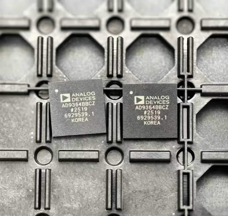

AD5686RARUZ-RL7
Brand: Analog Devices
Analog Devices AD5686RARUZ-RL7 is a analog & mixed-signal component designed for Precision Instrumentation and related applications. In stock at Superb Automation — request a quote for competitive pricing and fast delivery.
Product Specifications
AD5686RARUZ-RL7
Analog Devices — Analog & Mixed-Signal ICs
Product Overview
The AD5686RARUZ-RL7 from Analog Devices is a high-performance analog / mixed-signal IC providing precision signal acquisition, conversion, and conditioning. Analog Devices (ADI) is a world leader in high-performance analog, mixed-signal, and DSP ICs for instrumentation, healthcare, automotive, and communications.
Superb Automation partners with leading brands including Qorvo, TI, ADI, XILINX, NVIDIA, Intel, ST, MACOM, Renesas, and Coilcraft to provide complete BOM and supply-chain solutions.
Key Features
- High-resolution data conversion with excellent SNR and THD
- Wide dynamic range and high linearity across operating conditions
- Integrated voltage reference with low temperature drift
- Flexible digital interface — SPI, I2C, or parallel options
- Industrial/automotive temperature range with guaranteed specs
- Low power consumption with power-down modes
Key Specifications
| Resolution | bits |
| Channels | — |
| Sample Rate | kSPS |
| Interface | — |
| Supply Voltage | V |
| Operating Temp | °C |
| Package | — |
| INL | LSB |
| SNR | dB |
| THD | dB |
Applications
Precision Instrumentation
Industrial Process Control
Medical Imaging & Diagnostics
Automotive Sensor Interfaces
Communications Infrastructure
Test & Measurement
AD5686RARUZ-RL7: Four 16 Bit Channels With One Reference
What this part is
The AD5686R is a quad 16 bit voltage output converter with a 2.5 V reference inside the package and a serial peripheral interface that runs to 50 MHz. All four channels share the one reference, so they track each other, and a gain select pin sets the full scale to 2.5 V or 5 V. The part runs from a single 2.7 V to 5.5 V supply, and the logic supply pin allows a 1.8 V, 3 V or 5 V interface independent of the analogue rail.
Four channels in a 3 mm by 3 mm body with one reference is the arrangement that fits optical transceiver bias control, where several laser bias and modulation set points have to be programmed and held, and base station power amplifier bias, where the quiescent point of several stages is trimmed at production. A power-on reset with a selectable state brings the outputs up at zero scale or mid scale, and each channel can be powered down individually to 4 uA at 3 V.
Published figures that matter to a buyer
| Resolution | 16 bit on each channel |
| Channels | 4, voltage output |
| Internal reference | 2.5 V, 2 ppm per degree C typical |
| Output span | 2.5 V or 5 V, set by a gain pin |
| Relative accuracy | plus or minus 2 LSB maximum |
| Total unadjusted error | 0.1 percent of full scale maximum |
| Offset error | 1.5 mV maximum |
| Gain error | 0.1 percent of full scale maximum |
| Interface | serial peripheral interface, clock up to 50 MHz |
| Supply | 2.7 V to 5.5 V, separate logic supply |
| Power down | 4 uA per device at 3 V |
| Package | 16 lead TSSOP, tape and reel |
| Applications in the vendor list | optical transceivers, base station power amplifiers, programmable logic controller input output cards |
Where the headline numbers stop
Sixteen bits across a 5 V span is 76.3 uV per code and across 2.5 V it is 38.1 uV. The total unadjusted error of 0.1 percent of full scale on the 5 V span is 5 mV, which is 65.5 codes, so the converter is linear to a couple of codes and accurate to tens of codes. The offset error of 1.5 mV is 19.7 codes on its own. Anyone who needs the full 16 bits of absolute accuracy is looking at a different class of part; what this device delivers is 16 bits of resolution and monotonic behaviour with a small, trimmable error.
The interface rate is not the limit on update speed. Sixty four bits for four channels at 50 MHz is 1.28 us of bus time, which is fast enough that the settling of the output amplifier and the load are what decide how often the channels can actually change. The reference drift of 2 ppm per degree C on a shared reference moves all four channels together, which is an advantage in a ratio application and a problem in an absolute one, where a separate reference per channel would spread the error instead of correlating it.
Applications where it fits
- Optical transceiver bias and modulation set points, where several channels must be programmed and held in a small space.
- Base station power amplifier bias trimming, where the four channels track one reference.
- Programmable logic controller analogue output cards, where four channels per package reduces the part count.
- Industrial automation set points that need a monotonic 16 bit output with a known power-up state.
Two questions buyers ask
What state do the outputs come up in? The power-on reset brings the outputs to zero scale or mid scale depending on the RSTSEL pin, and they stay there until a valid write arrives. That choice has to match the safe state of the load, because a mid scale start on a bias input is very different from a zero start.
Can the channels be updated together? The interface supports writing one channel or several, and the point of a shared reference and a common clock is that simultaneous updates keep the relative levels fixed. A system that updates channels one at a time will see the outputs move in sequence, which for a bias tree can put the amplifier through a transient it would not otherwise see.
Sourcing notes and next step
The AD5686RARUZ-RL7 is the 16 lead TSSOP on a 13 inch reel, and the same die is offered in a 3 mm LFCSP. The family also covers 14 bit and 12 bit members with the same pinout, so a resolution change is a code change rather than a board change. The analog and mixed signal IC family page lists the converter line, the ADC and DAC cross reference page covers the substitution route across converter resolutions, and the RF component sourcing page sets out how bias converters are specified alongside the RF parts they control.
Request Quote — In Stock, 100% New & Original, Full Warranty
