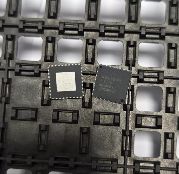
UCD3138RJAR
Brand: Texas Instruments
Texas Instruments UCD3138RJAR is a power management component designed for AI Servers & Low-Altitude Economy (Drone and UAV) and related applications. In stock at Superb Automation — request a quote for competitive pricing and fast delivery.
Product Specifications
UCD3138RJAR
Texas Instruments — Power Management & Signal Chain
Product Overview
The UCD3138RJAR from Texas Instruments is a power management / signal chain IC delivering high efficiency, precision regulation, and robust protection. Texas Instruments (TI) is a global leader in analog ICs, power management solutions, and embedded processors.
Superb Automation partners with leading brands including Qorvo, TI, ADI, XILINX, NVIDIA, Intel, ST, MACOM, Renesas, and Coilcraft to provide complete BOM and supply-chain solutions.
Key Features
- High-efficiency power conversion with low quiescent current
- Wide input voltage range with precision output regulation
- Integrated over-current, over-temperature, and short-circuit protection
- Small footprint packaging for space-constrained designs
- AEC-Q100 qualified options available for automotive applications
- Flexible sequencing and soft-start control
Key Specifications
| Input Voltage | V |
| Output Voltage | V |
| Output Current | A |
| Switching Frequency | kHz |
| Efficiency | % |
| Quiescent Current | µA |
| Topology | — |
| Package | — |
| Operating Temp | °C |
| Protection | — |
Applications
Industrial Automation
Automotive Electronics
Telecom Infrastructure
Server & Data Center Power
Medical Devices
Consumer Electronics
Request Quote — In Stock, 100% New & Original, Full Warranty
UCD3138RJAR: Digital controller for isolated power with three feedback loops
UCD3138RJAR is a digital power controller that closes up to three loops in hardware-assisted firmware in a VQFN body of 64 pins. It carries a 16 MHz error analogue-to-digital converter, a 14-bit effective digital-to-analogue converter, up to eight high-resolution pulse-width outputs with 250 ps resolution, switching to 2 MHz, and a 14-channel 12-bit 267 ksample/s general-purpose converter alongside them.
Order code and package
| Ordering string | UCD3138RJAR, RJA package, tape and reel |
| Package | 64-pin QFN, with the thermal pad as the main heat path |
| Ambient range | -40 C to 125 C |
| Thermal resistance | About 31.8 C/W junction to ambient in this package |
| Firmware | Configuration held in on-chip flash, loaded over the digital bus |
Electrical parameters that decide the application
| Control loops | Up to three independent feedback loops |
| Error converter | Up to 16 MHz, resolution configurable down to 1 mV per step |
| Pulse outputs | Up to eight, 250 ps pulse width resolution, 4 ns frequency and phase steps |
| Switching frequency | Up to 2 MHz |
| Comparators | Seven high-speed analogue comparators for cycle-by-cycle limiting |
| General converter | 14 channels, 12 bit, 267 ksample/s |
| Interfaces | Digital bus at up to 1 MHz, plus fault inputs and general-purpose comparators |
Points to check before this part goes on a BOM
A digital controller is chosen when the loop has to change with the operating point, and that is what three independent loops allow: one converter can hold a different response at light load than at full load without swapping components. The cost is firmware, and firmware is the part of the bill of materials that does not appear on the bill of materials. A board built around this part needs the configuration image versioned along with the hardware.
The error converter samples at up to 16 MHz and can drop its resolution to gain range, which is the mechanism that keeps a 1 mV step available near the setpoint without losing the ability to see a large transient. At 2 MHz switching that is eight samples per period, enough for a fast inner loop and not enough to replace an analogue comparator, which is why the part also carries seven of them for cycle-by-cycle limiting.
250 ps of pulse width resolution at 2 MHz is 0.05 percent of a period, and it is what makes a digitally controlled converter able to hold a tight output without an analogue post regulator. Below about 100 ps the jitter of the clock starts to matter more than the resolution, so the practical floor is set by the clock, not by the number in the feature list.
The 14-channel 12-bit converter is separate from the control path and is there for monitoring: input voltage, output voltage, two currents, and temperatures. It is slow by control standards and fast enough for telemetry, and keeping it separate means the housekeeping traffic does not disturb the loop timing.
Thermal resistance of about 32 C/W in a 64-pin QFN is a reminder that most of the heat in a digital controller is the gate drive. Driving eight outputs at high frequency with large MOSFETs puts the loss in the controller, so the pad, the vias and the copper are part of the drive budget. A controller that runs hot is usually driving more gate charge than the loop needs.
Fault handling is the reason isolated power supplies like this part: programmable fault counting, blanking time and external fault inputs let a board distinguish a transient from a real fault without adding comparators. That behaviour lives in the configuration image, so a replacement controller programmed with a different image is not the same part even when the top marking matches.
The configuration image is part of the part number in practice. Two boards built from the same silicon and the same bill of materials behave differently if one carries an older image, and the difference is usually in fault thresholds or soft-start timing rather than in steady-state regulation, so it passes a bench check and fails in the field. Keeping the image revision on the assembly drawing is the cheap insurance, and it is also what makes a replacement controller orderable rather than a gamble. The revision also has to be readable without powering the board, because the firmware cannot report its own version from a rail that will not come up, and that means a label on the assembly rather than a register read. A build that carries two images under one part number cannot be debugged from a serial number alone.
Where this order code fits
It fits an isolated DC to DC converter, a telecom rectifier, a server power shelf or a battery-facing charger, where the loop has to be tuned per operating point and the fault behaviour has to be defined rather than inherited. Teams comparing it with a neighbouring part start from our Power Management Cross Reference page, and teams replacing a part that has gone end of life start from the OEM Procurement page.
Questions buyers ask
Is the part programmed before delivery? The configuration lives in on-chip flash and is loaded in production. A replacement has to carry the same image, so the order needs to reference the programmed part number or the programme file, not just the bare device.
How many loops can run at once? Three independent loops, which is normally a voltage loop plus two current or share loops. The pulse outputs are shared between them, so the loop count and the output count are separate budgets.
Why does a digital controller need analogue comparators? Because a firmware loop cannot react inside one switching period. The comparators provide the cycle-by-cycle limit that protects the switch between samples, and the firmware handles everything slower than that.
SUPERB holds and sources this line for production and repair demand, quoted against the exact ordering string with date codes, packing and country of origin stated on the offer. When a part is moving, the Strategic Sourcing page sets out the checks that keep a substitute from failing on the bench.