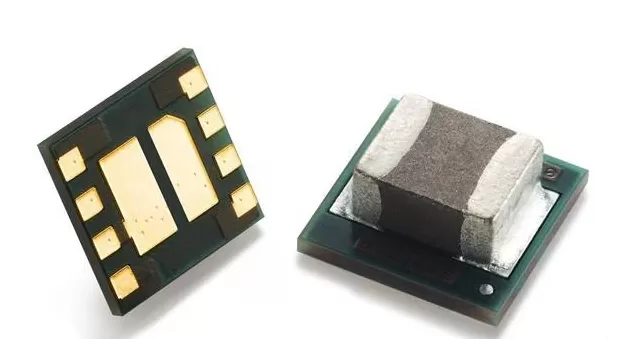
TPS82084SILR
Brand: Texas Instruments
Texas Instruments TPS82084SILR is a power management component designed for AI Servers & Low-Altitude Economy (Drone and UAV) and related applications. In stock at Superb Automation — request a quote for competitive pricing and fast delivery.
Product Specifications
TPS82084SILR
Texas Instruments — Power Management & Signal Chain
Product Overview
The TPS82084SILR from Texas Instruments is a power management / signal chain IC delivering high efficiency, precision regulation, and robust protection. Texas Instruments (TI) is a global leader in analog ICs, power management solutions, and embedded processors.
Superb Automation partners with leading brands including Qorvo, TI, ADI, XILINX, NVIDIA, Intel, ST, MACOM, Renesas, and Coilcraft to provide complete BOM and supply-chain solutions.
Key Features
- High-efficiency power conversion with low quiescent current
- Wide input voltage range with precision output regulation
- Integrated over-current, over-temperature, and short-circuit protection
- Small footprint packaging for space-constrained designs
- AEC-Q100 qualified options available for automotive applications
- Flexible sequencing and soft-start control
Key Specifications
| Input Voltage | V |
| Output Voltage | V |
| Output Current | A |
| Switching Frequency | kHz |
| Efficiency | % |
| Quiescent Current | µA |
| Topology | — |
| Package | — |
| Operating Temp | °C |
| Protection | — |
Applications
Industrial Automation
Automotive Electronics
Telecom Infrastructure
Server & Data Center Power
Medical Devices
Consumer Electronics
Request Quote — In Stock, 100% New & Original, Full Warranty
TPS82084SILR: 2 A step down module with the inductor inside the package
TPS82084SILR is a complete 2 A step down converter in a single package with the inductor and the controller already connected in a MicroSiP (SIL) body of 8 pins. It takes 2.5 V to 6 V in and delivers 0.8 V up to the input voltage at 2 A, switches at 2.4 MHz, draws 17 microamps in power save mode and fits in a 2.8 mm by 3.0 mm by 1.3 mm body.
Order code and package
| Order code read out | TPS82084 SIL R: 2 A member, SIL 8 pin MicroSiP, R tape and reel |
| Package | MicroSiP (SIL), 8 pins, 2.80 mm by 3.00 mm, 1.30 mm tall, inductor included |
| Carrier | 3000 pieces on a large reel |
| Operating temperature | minus 40 to plus 125 degrees Celsius |
| Sibling | TPS82085 is the 3 A member in the same footprint and the same pinout |
| Emission | CISPR 11 class B compliant as a module, which is one reason to use it instead of a discrete build |
| Extra functions | power good, output discharge, internal soft start, pre biased start up support |
Electrical parameters that decide the application
| Input voltage | 2.5 V to 6 V |
| Output voltage | 0.8 V to the input voltage, adjustable by divider |
| Output current | 2 A continuous, 3 A in the sibling part |
| Switching frequency | 2.4 MHz nominal, which keeps the output ripple small and the loop fast |
| Quiescent current | 17 microamps in power save mode at light load |
| Efficiency | up to 95 percent at the nominal operating point |
| High side switch current limit | 3.7 A minimum, 4.6 A typical, 5.5 A maximum |
| Duty cycle | 100 percent for the lowest dropout, which lets the output follow a falling input |
| Protection | hiccup mode short circuit after 32 consecutive current limit events, thermal shutdown |
| Feedback | an external divider sets the output, so the 0.8 V floor is the reference rather than a fixed option |
| Power good | open drain output, released when the output is inside regulation |
Family variants and how they differ
| TPS82084 | 2 A, the part on this page |
| TPS82085 | 3 A in the same body and pinout, the direct upgrade when the load grows |
| Footprint | both parts share the 2.8 mm by 3.0 mm outline, so the upgrade does not change the board |
| Module versus discrete | the inductor is inside, so there is no switch node loop to route and no inductor tolerance to add |
| Thermal | the module limits itself by junction temperature, and the 2 A rating assumes a copper pad under it |
Points to check before this part goes on a BOM
The 2 A rating is thermal, not electrical. The high side switch limits at 3.7 A minimum, so the silicon can pass more current than the package can cool. At 2 A in a 3.0 mm body the pad and the surrounding copper decide whether the part holds 2 A at 85 degrees ambient, and a quiet enclosure usually derates it.
The 3 A sibling fits the same pads. TPS82085 shares the body, the pinout and the footprint, so a load that grows from 1.5 A to 2.5 A can be covered without a board change. That is worth knowing before a board is released, because the alternative is a second board revision.
Hiccup mode needs 32 current limit events before it acts. That is deliberate, since a short burst of inrush should not shut the rail down, but it also means a hard short draws current for a measurable time before the converter folds back. On a rail feeding a connector that a user can touch, the upstream protection still has to exist.
The switch node is inside the package, so the usual switch node work disappears. What remains is the input capacitor placement, which still decides the ripple and the high frequency loop, and the output capacitor choice, which sets the transient. The module removes the inductor and the node routing, not the obligation to place capacitors well.
Two things to check before substituting a discrete buck. First, the module is qualified as a unit for CISPR 11 class B, while a discrete build has to earn that with its own filter. Second, the 2.4 MHz switching frequency sits in a band that some analogue front ends dislike, so check the emission at the frequency your own circuit is sensitive to.
The input capacitor placement is the remaining critical step. The module has the inductor and the switch node inside, so the high frequency loop is short, but the input capacitor still has to sit within a millimetre of the input pins to keep the ripple current out of the supply plane. A capacitor placed on the far side of a connector turns the module's clean emission into a board level problem.
The module is qualified as a unit for CISPR 11 class B. A discrete buck with the same silicon needs its own filter to reach the same result, and the filter is usually larger than the difference in cost. That is the honest reason to use a module on a dense board: the emission work is already done, and the remaining work is thermal.
Output ripple is set by the 2.4 MHz switching and the output capacitor, and it is small enough that most loads do not need a second stage. Where a rail feeds an analogue front end, the ripple at the switching frequency can still couple into a sensitive node, and a small LC filter after the module is cheaper than a linear post regulator.
The 6 V input ceiling is the first thing to check. A 5 V rail with a plus or minus 10 percent tolerance reaches 5.5 V and fits, while a 5.5 V rail itself does not. Modules in this family are aimed at rails derived from a higher bus, so the input is usually a 3.3 V or 5 V intermediate rather than a raw supply.
The module has no external compensation and no switch node to route, which removes the two most common sources of a buck that works on the bench and fails in production. What remains is the input capacitor placement and the thermal pad, and both are mechanical decisions that are easy to get right once.
Where this order code fits
These modules power optical transceiver modules, single board computers, solid state drives, metro data centre cards and radar boards, where the rail has to be small, quiet and assembled on a standard surface mount line. Teams comparing it with a neighbouring part start from our Power Management Cross Reference page, and teams replacing a part that has gone end of life start from the RF Component Sourcing page.
Questions buyers ask
Can I get 3 A from the 2 A part? No. The 2 A figure is the guaranteed continuous rating and it is thermal. The 3 A member, TPS82085, is the part to use and it drops into the same footprint.
Does it need an external inductor? No, the inductor is inside the package. Only the input and output capacitors and the feedback divider are external.
What happens on a shorted output? The converter limits current and enters hiccup mode after 32 events, then retries. It recovers on its own once the short clears.
What external parts does it need? Input and output capacitors and the feedback divider. The inductor, the switches and the compensation are inside the package.
Does it work from a 5 V rail with tolerance? Yes, 5.5 V is inside the 6 V maximum. A 5.5 V nominal rail with tolerance is outside it, so check the top of the tolerance band rather than the nominal value.
SUPERB holds and sources this line for production and repair demand, quoted against the exact ordering string with date codes, packing and country of origin stated on the offer. When a part is moving, the One Stop RF Supply page sets out the checks that keep a substitute from failing on the bench.