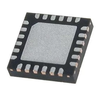
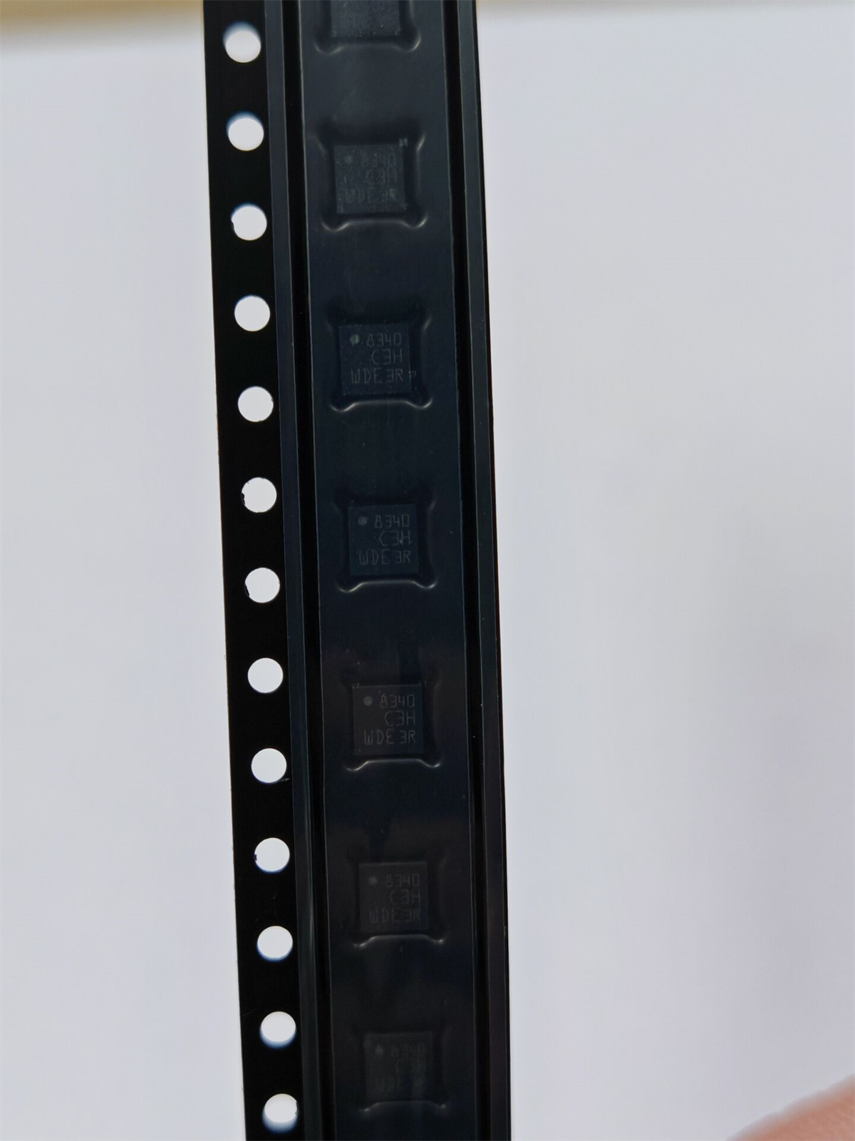
TPS54202HDDCR
Brand: Texas Instruments
Texas Instruments TPS54202HDDCR is a power management component designed for AI Servers & Low-Altitude Economy (Drone and UAV) and related applications. In stock at Superb Automation — request a quote for competitive pricing and fast delivery.
Product Specifications
TPS54202HDDCR
Texas Instruments — Power Management & Signal Chain
Product Overview
The TPS54202HDDCR from Texas Instruments is a power management / signal chain IC delivering high efficiency, precision regulation, and robust protection. Texas Instruments (TI) is a global leader in analog ICs, power management solutions, and embedded processors.
Superb Automation partners with leading brands including Qorvo, TI, ADI, XILINX, NVIDIA, Intel, ST, MACOM, Renesas, and Coilcraft to provide complete BOM and supply-chain solutions.
Key Features
- High-efficiency power conversion with low quiescent current
- Wide input voltage range with precision output regulation
- Integrated over-current, over-temperature, and short-circuit protection
- Small footprint packaging for space-constrained designs
- AEC-Q100 qualified options available for automotive applications
- Flexible sequencing and soft-start control
Key Specifications
| Input Voltage | V |
| Output Voltage | V |
| Output Current | A |
| Switching Frequency | kHz |
| Efficiency | % |
| Quiescent Current | µA |
| Topology | — |
| Package | — |
| Operating Temp | °C |
| Protection | — |
Applications
Industrial Automation
Automotive Electronics
Telecom Infrastructure
Server & Data Center Power
Medical Devices
Consumer Electronics
Request Quote — In Stock, 100% New & Original, Full Warranty
TPS54202H 28 V 2 A synchronous buck in a six pin SOT-23
The TPS54202HDDCR is a 4.5 V to 28 V input, 2 A synchronous step down converter in the six pin SOT-23 body. Both switches are inside, 148 milliohm on the high side and 78 milliohm on the low side, and the frequency is fixed at 500 kHz. The part carries its own loop compensation and a 5 millisecond internal soft start, so the external component count is an inductor, two capacitors and two resistors. That is the whole point of the part: it turns a wide input rail into 5 V or 3.3 V at 2 A with a footprint that fits under a connector.
The H suffix identifies the variant that is rated to 28 V rather than the 18 V of the earlier part in the same family, which is what lets it sit directly on a 24 V industrial bus. The control is peak current mode with an Eco-mode pulse skip at light load, and the current limit acts on both switches, with a hiccup response if the overload persists.
Key parameters taken from the SLVSDG7A document
| Input range | 4.5 V to 28 V operating, with VIN UVLO at 3.9 V to 4.4 V rising and 3.4 V to 3.9 V falling, 400 to 560 mV of hysteresis |
| Output current | 2 A continuous from a synchronous stage with 148 milliohm high side and 78 milliohm low side switches at 25 degrees |
| Switching frequency | Fixed 500 kHz, with no external resistor and no synchronisation pin |
| Feedback | 0.596 V typical, 0.581 V to 0.611 V, so a divider sets the output and the tolerance is about plus or minus 2.5 per cent before the divider tolerance |
| Quiescent current | 45 microamp while not switching, 2 microamp in shutdown with the enable held low |
| Light load | Eco-mode pulse skip with a 300 mA peak inductor current threshold at 24 V in and 5 V out into 15 microhenry |
| Soft start | 5 milliseconds internal, with no external capacitor |
| Enable pin | 1.35 V rising and 1.25 V falling, with 1 microamp of hysteresis current |
| Protection | Cycle by cycle current limit on both switches, hiccup mode after a persistent overload, overvoltage protection and thermal shutdown |
| Package | Six pin SOT-23, the DDC suffix in the catalogue string |
What a fixed 500 kHz costs and buys
A fixed frequency removes two decisions and one resistor. It also fixes the inductor and capacitor values that give a stable loop, which is why the vendor can integrate the compensation. The cost is that the switching loss is set by the part, not by the board, and 500 kHz at 28 V in is a real loss: the high side switch has to charge and discharge its own capacitance 500 thousand times a second, and that loss rises with the square of the input voltage. A 24 V to 5 V rail at 2 A runs noticeably hotter than a 12 V to 5 V rail at the same current, and the thermal pad under the six pin body is the only path out.
The current limit and the hiccup response
The high side limit protects the switch during a hard short, and the low side limit stops the inductor current from running away when the high side is off. If the overload lasts longer than the internal hiccup timer, the part shuts down, waits, and restarts, which converts a continuous short into a low duty cycle pulse train and keeps the die temperature bounded. On the bench the symptom is a rail that ticks rather than a rail that dies, and a scope on the switch node shows bursts separated by a long off time.
Where the part fits
Typical sockets are a 24 V industrial sensor or actuator board, a 12 V to 5 V rail for a small controller, and a point of load supply behind a 19 V or 24 V adapter. The 2 A rating with a 500 kHz fixed frequency is a good match for a 1.5 A to 2 A load, where the part runs at 75 to 100 per cent of rating and the inductor is still small. Above 2 A the family moves to a different body with a different thermal path.
The six pin SOT-23 is easy to place and hard to cool, so the copper area under the body is part of the specification rather than an afterthought. A board built with two square millimetres of copper under the part will not deliver 2 A at 85 degrees ambient, however good the silicon is.
Frequently asked questions
Can two parts be paralleled for 4 A. Not directly, since the fixed frequency and the internal compensation are not set up for current sharing, and the two loops will fight. The correct route is a single converter rated for the current.
Why is the feedback 0.596 V rather than a round 0.6 V. The internal reference is trimmed to that value, and the divider should be solved from 0.596 V rather than from 0.6 V, which is a 0.7 per cent difference at the output and enough to matter on a 1 per cent rail.
What replaces it if the reel is short. The 28 V family has a 3 A member in a different body, and the 18 V member is pin compatible in some boards. Our desk checks the input rating first, since a 24 V bus cannot use the 18 V part, and lists the options on power management cross reference and component lead time solutions.