


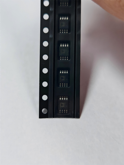

TMP108AIYFFR
Brand: Texas Instruments
Texas Instruments TMP108AIYFFR is a power management component designed for AI Servers & Low-Altitude Economy (Drone and UAV) and related applications. In stock at Superb Automation — request a quote for competitive pricing and fast delivery.
Product Specifications
TMP108AIYFFR
Texas Instruments — Power Management & Signal Chain
Product Overview
The TMP108AIYFFR from Texas Instruments is a power management / signal chain IC delivering high efficiency, precision regulation, and robust protection. Texas Instruments (TI) is a global leader in analog ICs, power management solutions, and embedded processors.
Superb Automation partners with leading brands including Qorvo, TI, ADI, XILINX, NVIDIA, Intel, ST, MACOM, Renesas, and Coilcraft to provide complete BOM and supply-chain solutions.
Key Features
- High-efficiency power conversion with low quiescent current
- Wide input voltage range with precision output regulation
- Integrated over-current, over-temperature, and short-circuit protection
- Small footprint packaging for space-constrained designs
- AEC-Q100 qualified options available for automotive applications
- Flexible sequencing and soft-start control
Key Specifications
| Input Voltage | V |
| Output Voltage | V |
| Output Current | A |
| Switching Frequency | kHz |
| Efficiency | % |
| Quiescent Current | µA |
| Topology | — |
| Package | — |
| Operating Temp | °C |
| Protection | — |
Applications
Industrial Automation
Automotive Electronics
Telecom Infrastructure
Server & Data Center Power
Medical Devices
Consumer Electronics
Request Quote — In Stock, 100% New & Original, Full Warranty
TMP108AIYFFR one degree digital temperature sensor with a programmable limit window in a six ball WCSP
The TMP108AIYFFR is a digital temperature sensor in a six ball wafer level package measuring 1.2 by 0.8 millimetres, with a supply range of 1.4 to 3.6 volts, a 12 bit reading at 0.0625 degrees per code, and a programmable limit window that asserts an alert on an under temperature or an over temperature event without the host reading the register at all. The interesting part of the specification is the supply floor of 1.4 volts, which is what puts this device on rails that other sensors cannot reach.
The document prints 0.75 degrees maximum accuracy from minus 20 to plus 85 degrees and 1 degree maximum from minus 40 to plus 125 degrees, with six microamps of active current as a maximum over the upper range. Those two numbers define the application: a battery powered product that has to watch its own temperature continuously without spending measurable energy, on a rail that may be a single cell or a low voltage domain rather than 3.3 volts.
Key parameters taken from the TMP108AIYFFR document
| Accuracy | Plus or minus 0.75 C maximum from minus 20 to plus 85 C, plus or minus 1 C maximum from minus 40 to plus 125 C |
| Supply | 1.4 to 3.6 V, which reaches a single cell rail and a 1.8 V domain |
| Current | 6 microamps active maximum over minus 40 to plus 125 C |
| Resolution | 12 bit, 0.0625 C per code |
| Interface | SMBus and two wire, with the SMBus alert function |
| Addressing | Up to four devices on one bus |
| Limit window | Dynamically programmable under and over temperature limits with alert output |
| Package | DSBGA, six balls, 1.20 by 0.80 mm nominal body |
| Range | Specified over minus 40 to plus 125 C |
| Conversion | Continuous conversion at a programmable rate, the alert works without a host read |
| Supply decoupling | A single small capacitor at the ball, no other external components |
| Order code facts | TMP108AIYFFR, YFF six ball DSBGA, tape and reel, catalog grade |
| Placement | Small enough to sit inside a phone board next to the battery or the modem, where a SOT-23 does not fit |
The table above is read from the vendor document, not from a distributor summary. Where a window is printed, the window is what a production test should use, and the typical value is only a starting point for the first article.
Where the numbers matter in a real build
The alert window is what makes this part useful in a battery powered product. Instead of polling the bus every second, the host writes an under limit and an over limit once and then sleeps; the part converts continuously and drives the alert pin when either limit is crossed. The document prints the default limits and the programmable range, and the firmware has to clear the alert explicitly, because a latched alert that is never cleared looks like a permanent fault on the next boot. The first article should verify the clear sequence and the behaviour across a sleep and wake cycle, not just the trip point.
A 1.4 volt supply floor is unusual and it changes the level shifting question. On a board where the host runs at 1.8 volts and the sensor sits on a 1.5 volt rail, the bus pull ups go to the lower rail and the host has to accept a lower high level, or the pull ups go to the higher rail and the sensor input has to tolerate it. Neither is a problem by itself, but the choice has to be made once and reflected in the pull up placement, because the default reference board assumes one rail for both.
The wafer level package has no compliant leads, so the assembly process decides the yield. A six ball body at 0.4 millimetre pitch needs a stencil aperture and a reflow profile that the contract support has qualified, and the part should not be the first 0.4 millimetre component on a new line. The other practical point is inspection: the balls are under the die and cannot be seen, so the process control is the placement accuracy and the paste volume, checked by x ray on the first article rather than by eye.
The accuracy window is asymmetric in a way that matters for a battery charger. Between minus 20 and plus 85 degrees the part holds 0.75 degrees, and above 85 degrees it opens to 1 degree. A charger that uses the reading to fold back current at 45 degrees has plenty of margin; a protection circuit that trips at 100 degrees has to allow for the wider window plus the self heating of the sensor sitting next to the power path, which is usually larger than the sensor error itself.
- Alert trip and clear, across a sleep and wake cycle, on the production firmware rather than a test image.
- Reading against a reference thermometer at three points inside the 0.75 degree window and one point outside it.
- Current draw in the continuous conversion mode the product will actually use.
- Bus behaviour with all four addresses populated, including the alert line arbitration.
- Placement against the heat source, with the self heating of the surrounding copper included.
- First article x ray of the six ball joint array and the paste volume record from the line.
Which projects this part fits
This part fits smartphone and tablet thermal management, battery pack and charger monitoring, thermostat and HVAC control, wearable and hearable products, and any board where the temperature sensor has to live on a 1.8 volt or single cell rail inside a very small board area. For SUPERB customers in medical handhelds and RF FrontEnd modules the small body and the low supply floor are the two reasons it appears in a bill of materials, and the SMBus alert means the host processor does not have to poll.
Questions that come up before a purchase order is released
Can this part run from a single lithium cell directly?
The supply range starts at 1.4 volts, so a cell that stays above that level through its discharge curve is inside the printed range. The document still specifies the accuracy over the full 1.4 to 3.6 volt band, but a cell near the end of discharge is close to the floor, so the board should check the accuracy at the lowest rail the product will actually see rather than at nominal.
How many devices fit on one bus?
Four, set by the address configuration. The SMBus alert function allows the host to identify which device raised the alert, so four sensors on one bus do not need four interrupt lines, which is usually the reason to choose this part over a plain two wire sensor.
Does the alert latch?
The alert stays asserted until the host clears it, and the clear sequence is printed in the document. A board that relies on the alert as an interrupt must clear it inside the handler, otherwise the line stays low and the next event is invisible.
What accuracy should the production test use?
The 0.75 degree figure is a maximum over minus 20 to plus 85 degrees, so a test at room temperature should see less than that. Testing against a maximum rather than a typical is what keeps a good unit from being scrapped, and testing at two temperatures is what catches a part that is offset rather than noisy.
Is a 0.4 millimetre pitch package a problem for a normal assembly line?
It is a standard wafer level package and most lines run it, but it needs a qualified stencil and a placed, not dispensed, paste process. The question to ask the contract support is whether the line has run a six ball 0.4 millimetre body in the last year, not whether it can in principle.
How SUPERB handles this line
We supply the TMP108AIYFFR on original tape and reel, and we handle the moisture and ESD side of a wafer level body as a standard part of the incoming flow. Where the board is choosing between sensor families, the power management cross reference page lists the digital sensors by bus, supply and accuracy. Where the question is how to keep a small body part available across a long production life, component obsolescence management sets out the options, and incoming inspection plan covers what to check on arrival.