
ISO1450DWR
Brand: Texas Instruments
Texas Instruments ISO1450DWR is a power management component designed for AI Servers & Low-Altitude Economy (Drone and UAV) and related applications. In stock at Superb Automation — request a quote for competitive pricing and fast delivery.
Product Specifications
ISO1450DWR
Texas Instruments — Power Management & Signal Chain
Product Overview
The ISO1450DWR from Texas Instruments is a power management / signal chain IC delivering high efficiency, precision regulation, and robust protection. Texas Instruments (TI) is a global leader in analog ICs, power management solutions, and embedded processors.
Superb Automation partners with leading brands including Qorvo, TI, ADI, XILINX, NVIDIA, Intel, ST, MACOM, Renesas, and Coilcraft to provide complete BOM and supply-chain solutions.
Key Features
- High-efficiency power conversion with low quiescent current
- Wide input voltage range with precision output regulation
- Integrated over-current, over-temperature, and short-circuit protection
- Small footprint packaging for space-constrained designs
- AEC-Q100 qualified options available for automotive applications
- Flexible sequencing and soft-start control
Key Specifications
| Input Voltage | V |
| Output Voltage | V |
| Output Current | A |
| Switching Frequency | kHz |
| Efficiency | % |
| Quiescent Current | µA |
| Topology | — |
| Package | — |
| Operating Temp | °C |
| Protection | — |
Applications
Industrial Automation
Automotive Electronics
Telecom Infrastructure
Server & Data Center Power
Medical Devices
Consumer Electronics
Request Quote — In Stock, 100% New & Original, Full Warranty
ISO1450DWR: isolated 50 Mbps RS-485 transceiver with the reinforced barrier
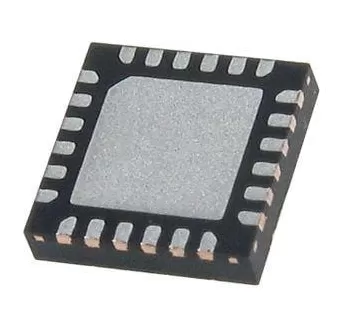
ISO1450DWR is the fastest member of the isolated RS-485 line, half duplex in a wide body 16 pin SOIC, with the logic side and the bus side on separate supplies and a reinforced barrier between them in a SOIC body of 16 pins. It carries 50 Mbps, loads the bus at one eighth of a unit load so 256 nodes fit, and protects the bus pins to plus or minus 30 kV human body model, plus or minus 16 kV IEC 61000-4-2 contact discharge and plus or minus 4 kV IEC 61000-4-4 fast transient burst. Driver propagation is 19 ns typical and 41 ns maximum with 1 ns typical and 6 ns maximum of pulse width distortion, common mode transient immunity is 100 kV per microsecond typical, the receiver is fail safe on an open, shorted or idle bus, and the part is characterised from minus 40 to plus 125 degrees.
Order code and package
| ISO1450DWR | wide body DW package, 16 pins, 10.30 mm by 10.30 mm, reinforced barrier, 50 Mbps half duplex. The addendum prints the tube at 40 pieces and the R string on a 2000 piece large reel, but the quantity column drifts by one row in this print, so the reel count is confirmed on the label |
| ISO1450DW | the tube row of the same body |
| ISO1450BDWR | the basic barrier version of the same 50 Mbps member, 6000 VPK of surge instead of 10000 |
| ISO1430DWR | the 12 Mbps member in the same body and the same reinforced barrier, and the one that matches a PROFIBUS segment |
| ISO1452DWR | the full duplex member at 50 Mbps, four bus pins instead of two and the same package |
Electrical parameters that decide the application
| Logic side supply | 1.71 V to 1.89 V for a 1.8 V rail, or 2.25 V to 5.5 V for the higher rails, so the part can sit directly on an FPGA or a 1.8 V controller port |
| Bus side supply | 3 V to 5.5 V, with 5 V for the PROFIBUS condition. The two sides are independent supplies across the barrier |
| Signalling rate | 50 Mbps, the top of the family, with 12 Mbps and 500 kbps members in the same package |
| Node count | one eighth of a unit load, up to 256 nodes, which removes a repeater from a long trunk |
| Bus protection | plus or minus 30 kV human body model, plus or minus 16 kV IEC 61000-4-2 contact discharge and plus or minus 4 kV IEC 61000-4-4 burst on the bus pins |
| Driver switching | 19 ns typical and 41 ns maximum of propagation, pulse width distortion 1 ns typical and 6 ns maximum, rise and fall 4.7 ns typical at a 5 V bus and 7.8 ns at 3.6 V, which is the fastest edge in the family |
| Common mode transient immunity | 100 kV per microsecond typical across the barrier |
| Isolation, repetitive peak | 1500 VPK, with 1060 VRMS or 2121 VDC of working voltage |
| Isolation, transient | 7071 VPK, tested at 1.2 times that value for one second on every unit |
| Isolation, surge | 10000 VPK on this reinforced string against 6000 VPK on the B version, which is the only electrical difference between the two strings |
| Spacing | more than 8 mm of clearance and creepage, more than 17 um of insulation thickness and a tracking index above 600, with a barrier capacitance of about 1 pF |
| Certifications | 5000 VRMS for one minute per UL 1577, DIN EN IEC 60747-17 for the VDE file and the IEC 62368-1, 60601-1 and 61010-1 standards, with CQC, TUV and CSA listed |
| Fail safe | the receiver holds a defined output with the bus open, shorted or idle, so a pulled connector does not feed noise into the controller |
Family variants and how they differ
| Against the B version | the same rate, the same package and the same pinout, with 10000 VPK of surge against 6000 and a higher routine test multiple. A product that claims reinforced isolation must name this string |
| 1450 against 1430 | 50 Mbps against 12 Mbps. The faster part is not a drop in upgrade for a fieldbus segment, because the cable and the termination were sized for the slower rate |
| 1450 against 1452 | half duplex against full duplex. The 1452 needs four bus pins and a four wire field cable, which most installations do not have |
| Against a non isolated transceiver | a non isolated part costs a fraction of this one and needs no bus side supply, but it cannot bridge a ground difference. The barrier is the product |
| Against a digital isolator plus a transceiver | two parts take more area but allow a transceiver the customer already qualified. The single package wins on area and on the number of joints |
Points to check before this part goes on a BOM
This string and ISO1450BDWR are the same transceiver with two different barriers. The reinforced version gives 10000 VPK of surge and applies 1.6 times the working voltage in the routine test, the basic version gives 6000 VPK and 1.2 times. A quotation that mixes the two strings is quoting two different safety claims at almost the same price, and the safety file is the document that decides which one is allowed.
The 50 Mbps rate in an isolated package is a niche requirement: most isolated field buses run far slower, and the members that matter in volume are the 12 Mbps and the 500 kbps ones. The fast member is for a short isolated link between two controllers, an isolated backplane segment or a test fixture, where the cable is short enough to support the rate.
The edge rate is the fastest in the family, 4.7 ns at a 5 V bus. Fast edges radiate, and an isolated port on a switching cabinet is exactly where emissions are measured. A port that does not need 50 Mbps should use the slower member, both for emissions and for the larger timing margin that comes with the slower driver.
The addendum print for this family is offset row by row, so the tube and reel quantities do not sit on the part number lines. The 40 piece tube and the 2000 piece reel are consistent across the family and across revisions, but a purchase order should carry the quantity independently rather than rely on the row alignment of the PDF.
The barrier capacitance is about 1 pF, and that is the number that decides how much common mode current a fast transient pushes across the barrier. A 1 pF barrier with a 100 kV per microsecond transient couples a current the receiver has to reject, which is exactly what the common mode transient immunity figure describes.
Isolation separates signals and not power. The bus side needs its own rail, usually from a small transformer driver and a transformer, and a port quoted without that block is an incomplete port. It is also the block that decides the cost of the isolated side, more than the transceiver does.
Where a 50 Mbps isolated port is used
Test fixtures, isolated backplane segments and short links between two controllers are the realistic uses. The barrier is there to break a ground loop or to protect a measurement front end, and the rate is there because the protocol is fast and the cable is short.
In those cases the reinforced string is usually required, because the reason for the barrier is a safety or a measurement integrity claim rather than a cost driven ground shift.
What the order code decides
The string reads ISO1450 for the 50 Mbps half duplex member, no B for the reinforced barrier, DW for the wide body package and R for the reel of 2000. The B in the same position changes the surge rating and nothing else.
A change from 1450 to 1430 or 1410 is a slower bus in the same package, and a change to 1452 is a four wire bus. None of those is a substitution a purchaser can make without the engineering file being rechecked.
Where this order code fits
Short isolated links between controllers, isolated backplane segments, test fixtures and measurement front ends where the barrier is a safety or an integrity requirement and the protocol is fast. Teams comparing it with a neighbouring part start from our Pin to Pin Cross Reference page, and teams replacing a part that has gone end of life start from the Component Lead Time Solutions page.
Questions buyers ask
What is the difference to the B string? The barrier. This string carries 10000 VPK of surge and applies 1.6 times the working voltage in the routine test, the B string carries 6000 VPK and 1.2 times.
Is 50 Mbps realistic on a field cable? On a short cable inside a cabinet, yes. On a long field segment the cable sets the rate, and the 12 Mbps member is the realistic choice.
Does it need two supplies? Yes. The logic side runs from 1.71 V to 5.5 V and the bus side from 3 V to 5.5 V, and the bus side supply comes from an isolated converter.
How many nodes fit on the isolated side? 256, at one eighth of a unit load, the same loading as the non isolated parts of this rate.
SUPERB holds and sources this line for production and repair demand, quoted against the exact ordering string with date codes, packing and country of origin stated on the offer. When a part is moving, the How to Verify a Drop in Replacement page sets out the checks that keep a substitute from failing on the bench.