

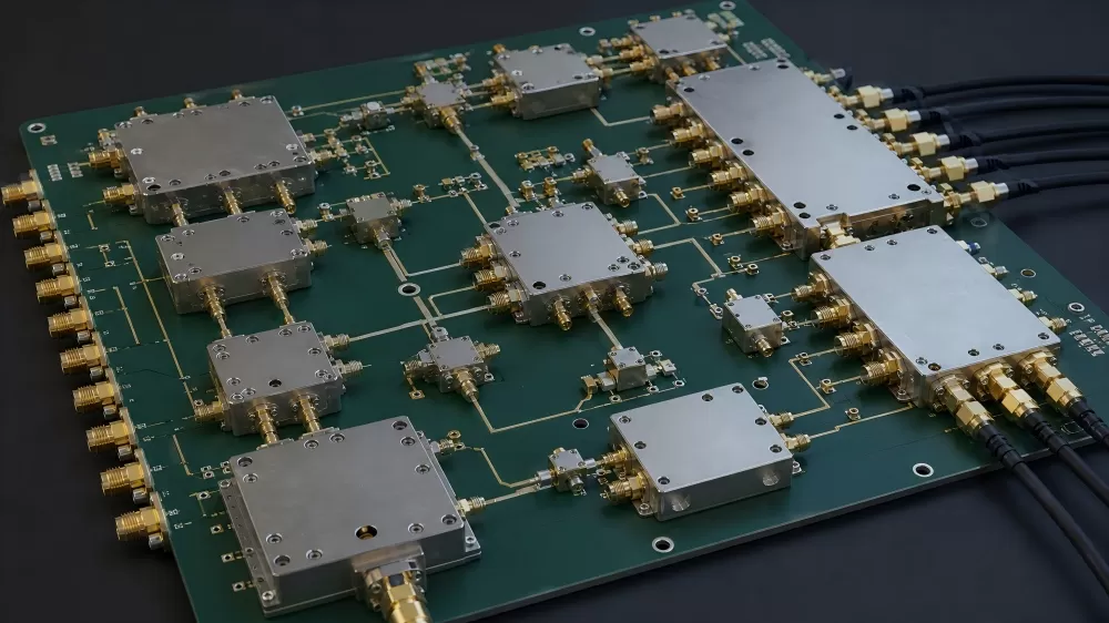
RF Isolators and Circulators for Transceiver Front Ends


Product Specifications
Product Overview
An isolator is a circulator with a termination on the third port. In a transceiver front end the part passes the transmit signal toward the antenna, absorbs the power that comes back from a mismatched load, and keeps that reflected energy out of the final amplifier stage. A circulator does the same routing without the internal load, so the third port stays available for a receive path, a calibration path or an external termination.
The parts on this page are ferrite junction devices on surface mount carriers. The junction diameter sets both the power the part will carry and the loss it can hold: a 10 mm junction covers 20 W class transmit paths and receiver protection, while a 20 mm junction carries 100 W to 300 W average with peak power in the kilowatt range. Insertion loss across the parts listed runs from 0.18 dB to 0.35 dB, with isolation from 20 dB to 25 dB.
Bands run from 860 MHz to 960 MHz for UHF radio and industrial links, through 1805 MHz to 2690 MHz for LTE and 5G sub 6 radio units, up to 3300 MHz to 3800 MHz for C band radios. Rotation direction is part of the specification, not a marking detail: a clockwise junction will not take the place of a counter clockwise junction with the same footprint, so the table below lists the type and the package for each part number.
Key Specifications
| Parameter | Isolator, robust lead | Circulator, 10 mm | Circulator, 20 mm |
|---|---|---|---|
| Frequency coverage | 1805 MHz to 3600 MHz in sub bands | 2110 MHz to 3800 MHz in sub bands | 860 MHz to 3600 MHz in sub bands |
| Insertion loss | 0.20 dB to 0.30 dB | 0.25 dB to 0.30 dB max | 0.18 dB to 0.35 dB max |
| Isolation | 20 dB to 23 dB min | 20 dB to 21 dB min | 20 dB to 25 dB min |
| Return loss | 20 dB to 23 dB min | 20 dB to 23 dB min | 20 dB to 24 dB min |
| Average power | 5 W to 30 W of reverse power | 20 W to 60 W | 100 W to 300 W |
| Peak power | quoted per part from the maker data sheet | 100 W to 480 W | 500 W to 1000 W |
| Third port | internal load, absorptive | open port for a receive path | open port for a receive path |
| Mounting | robust lead SMT | drop in SMT carrier, 10 mm | drop in SMT carrier, 20 mm |
Included Models and Order Codes
The table below lists the junction parts we quote most often for radio units, radar front ends and instrument signal chains. Frequency range, insertion loss and isolation are copied from the maker data sheet for the junction; where a part is listed as typical rather than max, the figure is the typical value over the band.
| Part Number | Type | Frequency | Insertion Loss | Isolation | Power | Package |
|---|---|---|---|---|---|---|
| SKYFR-001436 | Isolator | 1805 to 1880 MHz | 0.30 dB max | 20 dB min | 5 W reverse class | Robust lead SMT |
| SKYFR-001437 | Isolator | 1930 to 1995 MHz | 0.20 dB typ | 23 dB min | 5 W reverse class | Robust lead SMT |
| SKYFR-001439 | Isolator | 2300 to 2400 MHz | 0.25 dB typ | 20 dB min | 5 W reverse class | Robust lead SMT |
| SKYFR-001512 | Isolator | 3400 to 3600 MHz | 0.20 dB typ | 23 dB min | 5 W reverse class | Robust lead SMT |
| SKYFR-000767 | Circulator | 860 to 960 MHz | 0.35 dB max | 20 dB min | 140 W avg, 500 W peak | 20 mm SMT |
| SKYFR-001369 | Circulator | 1805 to 1880 MHz | 0.18 dB max | 23 dB min | 140 W avg, 800 W peak | 20 mm SMT |
| SKYFR-001058 | Circulator, CCW | 1915 to 2010 MHz | 0.19 dB max | 23 dB min | 140 W avg, 800 W peak | 20 mm SMT |
| SKYFR-000847 | Circulator | 2300 to 2400 MHz | 0.25 dB max | 23 dB min | 140 W avg, 800 W peak | 20 mm SMT |
| SKYFR-001502 | Circulator | 2400 to 2500 MHz | 0.20 dB max | 23 dB min | 300 W avg, 500 W peak | 20 mm SMT |
| SKYFR-002076 | Circulator | 2496 to 2690 MHz | 0.25 dB max | 22 dB min | 150 W avg, 800 W peak | 20 mm SMT |
| SKYFR-001103 | Circulator | 3400 to 3600 MHz | 0.30 dB max | 25 dB min | 100 W avg, 1000 W peak | 20 mm SMT |
| SKYFR-001901 | Circulator | 2496 to 2690 MHz | 0.30 dB max | 20 dB min | 20 W avg, 160 W peak | 10 mm SMT |
| SKYFR-001922 | Circulator | 3400 to 3600 MHz | 0.30 dB max | 20 dB min | 50 W avg, 200 W peak | 10 mm SMT |
| SKYFR-002085 | Circulator | 3300 to 3800 MHz | 0.25 dB max | 20 dB min | 30 W avg, 300 W peak | 10 mm SMT |
Key Features
Reflected power goes into the load – the third port of an isolator is terminated inside the package, so energy coming back from a detuned antenna or an open connector is absorbed instead of returning to the amplifier output.
Band edges are hard limits – a ferrite junction is tuned to its band. The 2300 to 2400 MHz part and the 2496 to 2690 MHz part are the same size and the same power class, and neither will work in the band of the other.
Rotation direction is fixed – signal travels port 1 to port 2 to port 3 in the direction stated on the data sheet. A counter clockwise part placed where a clockwise part is expected will invert the transmit and receive paths on the board.
Loss that fits the budget – 0.18 dB to 0.35 dB of insertion loss is a direct subtraction from the transmit power and from the receive noise figure, which is why the C band parts are specified at 0.20 dB and below on the larger junctions.
Power class follows the junction – a 10 mm junction holds 20 W to 60 W average and a 20 mm junction holds 100 W to 300 W, with peak ratings from 100 W to 1000 W. Peak power at the pulse width of the application is the figure that decides if a smaller junction can be used.
Temperature stable over the band – the junction parts are rated from -40 C to +105 C or +125 C, and the insertion loss and isolation figures in this table hold over that range, not only at 25 C.
Surface mount carrier – robust lead and drop in carriers are placed and reflowed like any other SMT part, which removes the hand soldering step that connectorized isolators need on a radio board.
Applications
These junctions are quoted for boards that transmit and receive through the same antenna, typically where: The junction sits on the same board as the amplifier and the filter, so it is quoted together with the SUPERB PCB and the SUPERB PCBA build for that board.
Radio unit transmit path – a 3.5 GHz radio unit places the circulator between the power amplifier and the antenna filter, where 23 dB of isolation keeps a reflection from a detuned antenna from reaching the amplifier output.
Radar and defence front ends – a 20 mm junction carries the peak power of a pulse transmitter while the isolated port protects the receive chain, and the part is chosen on peak power and loss in the band rather than on average power alone.
Test and measurement – a bench setup uses the third port to sample the forward and reflected wave, which is how return loss is measured without adding a directional coupler to the instrument.
Sourcing and Cross-Reference
A ferrite junction is a band device, not a general purpose part. When an isolator on a bill of materials goes end of life, the replacement has to match the band edges, the rotation direction, the junction diameter and the power class, and it has to survive the same reflected power as the part it replaces. Sorting candidates by case size first usually produces a part that fits the footprint and fails on band or on peak power.
Our search starts from the electrical envelope: frequency range, average and peak power, isolation, insertion loss and the temperature at the top of the band. Once a junction matches on those numbers, the mechanical outline is checked against the land pattern on the board, because the lead position on a robust lead carrier is not the same as the pad ring on a drop in carrier of the same diameter.
Where the original junction is no longer available, the usual answer is a device from another junction maker with the same outline and equal or better loss, quoted with data measured across the band. The sourcing route for these parts is described on our RF component sourcing page, and the replacement path for bands that the original maker has dropped is on obsolete RF part replacement.
For volume builds, SUPERB Assembly support covers the placement of the ferrite carrier, the ground via array under the junction and the reflow profile the package needs.
Q: Can you supply a circulator or isolator for a band that the original maker has dropped?
A: Yes. Send the band edges, the rotation direction, the average and peak power, the junction diameter and the land pattern, and the SUPERB Tech team will confirm which junction fits and quote it with measured data for the band.
Why Buyers Source Isolators and Circulators Through SUPERB
- Band and rotation confirmed before quoting: the first two questions are the frequency edges and the direction of travel, because those two answers remove most of the parts that would otherwise be quoted and rejected.
- Reflected power checked against the load: the reverse power the part has to absorb is compared with the rating on the data sheet at the ambient temperature of the enclosure, not at 25 C on a bench.
- Loss kept inside the chain budget: candidates are ranked by insertion loss in the band, so a 0.3 dB part is not offered where the link budget was built on a 0.2 dB junction.
- Test data with the quotation: measured insertion loss and isolation for the band are sent with the price, so the part can be approved without a separate sample request.
Related Product Families
This page is part of the component range we supply for industrial, telecom, medical and defence builds. Continue with: Frequency converters and sources, RF power dividers and directional couplers, Digital step attenuators, RF gain blocks and low noise amplifiers, RF component sourcing.