

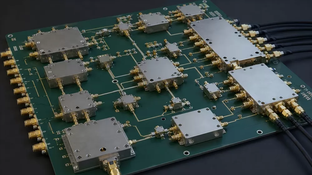
RF Power Dividers and Directional Couplers for Signal Routing


Product Specifications
Product Overview
A splitter divides one signal into two or four equal paths, and the first number that matters is not the split but the loss above it. A two way splitter hands each port half the power, which is 3 dB by definition, so the useful figure is the insertion loss on top of that 3 dB. A part quoted at 0.5 dB adds half a decibel to each path, and on a receiver front end with a fixed noise budget that is a real cost. A four way splitter starts from 6 dB, and the extra loss is quoted the same way.
Isolation is the second number and it decides whether the ports can see each other. In a two way splitter, isolation is what stops a reflection from one antenna reaching the other receiver, and it is why a part with 35 dB isolation is used for two receivers on one antenna while a part with 20 dB is enough for a lab fan out. Amplitude and phase balance then decide whether a differential or an I and Q pair stays matched, and both are quoted in the same table as the loss for that reason.
A directional coupler samples a fraction of the power travelling one way and rejects the power travelling the other way. Coupling sets the sample level, typically 20 dB down, and directivity sets how well the reverse wave is rejected. The difference between a 20 dB coupler with 22 dB directivity and one with 27 dB is what a return loss measurement can resolve, so the directivity figure is quoted with the frequency band rather than as one number for the whole range.
Key Specifications
| Parameter | Two way splitter | Four way splitter | Directional coupler |
|---|---|---|---|
| Frequency range | 0.2 MHz to 1000 MHz | 0.002 MHz to 20 MHz | 0.1 MHz to 2000 MHz |
| Split | 3 dB per port | 6 dB per port | 20 dB coupled port |
| Loss above the split | 0.2 dB to 0.5 dB typical | 0.2 dB typical | 0.2 dB to 0.7 dB mainline |
| Isolation or directivity | 25 dB to 35 dB typical | 33 dB typical | 22 dB to 27 dB typical |
| Amplitude balance | 0.1 dB typical | 0.05 dB typical | coupling flatness within 1.5 dB |
| Phase balance | 0.5 to 2 degrees typical | 0.3 degrees typical | 180 degree version available in the two way family |
| Power as a splitter | 1 W | 1 W | 4 W below 700 MHz, 2 W to 1300 MHz |
| Connector or package | SMA, BNC, N type | BNC | surface mount 6 lead, or coaxial body |
Included Models and Order Codes
The models below are the splitters and couplers quoted most often for lab benches, antenna distribution, power monitoring and return loss measurement. State the frequency band, the number of ways, the power level, the connector or footprint and the isolation you need, and the part and its mounting are confirmed together.
| Part Number | Function | Frequency Range | Loss or Coupling | Isolation or Directivity | Package or Connector |
|---|---|---|---|---|---|
| ZFSC-2-4+ | 2 way, 0 degree | 0.2 to 1000 MHz | 0.5 dB insertion loss typical | 25 dB isolation typical | coaxial, BNC or SMA |
| ZSC-2-4+ | 2 way, 0 degree | 10 to 1000 MHz | 0.2 dB insertion loss typical | 35 dB isolation typical | coaxial, BNC |
| ZFSCJ-2-4+ | 2 way, 180 degree | 50 to 1000 MHz | 1.4 dB insertion loss typical | 28 dB isolation typical | coaxial, SMA |
| ZSC-4-2+ | 4 way, 0 degree | 0.002 to 20 MHz | 0.22 dB above 6 dB typical | 33 dB isolation typical | coaxial, BNC |
| ADC-20-13+ | directional coupler | 450 to 1000 MHz | 20.7 dB coupling, 0.2 dB mainline loss | 25 dB directivity typical | 6 lead surface mount |
| ADC-20-132+ | directional coupler | 100 to 1300 MHz | 20 dB coupling, 0.4 dB mainline loss | 22 dB directivity | surface mount |
| ZFDC-20-5+ | directional coupler | 0.1 to 2000 MHz | 20 dB coupling, 0.7 dB mainline loss | 27 dB directivity typical | coaxial body |
Key Features
Loss quoted above the split – the insertion loss is given after the 3 dB or 6 dB division, so the real cost on the signal path is visible without arithmetic on the bench.
Isolation for shared antennas – a part with 35 dB isolation keeps two receivers on one antenna from seeing each other, while a 20 dB part is enough for a fan out into separate instruments.
Phase balance stated – the 180 degree version is listed in the same family as the in phase parts, so a balanced pair or a push pull stage can be built from one order line.
Frequency band with every figure – isolation and directivity fall at the band edges, so each row states the band its figures belong to rather than a single headline number.
Power rating as a splitter – the rating is given for the sum port with the other ports terminated, which is the condition a transmitter sees, and the four way part is derated at the low band edge.
Surface mount and coaxial together – a 6 lead coupler for a board and a coaxial body for a rack panel are both listed, so a prototype and a production unit can use the same electrical part.
Connector options on one model – the two way splitters are offered with BNC, SMA and N type connectors under the same model root, which keeps the electrical specification identical across a bench and a field build.
Mainline loss separated from coupling – the coupler rows give mainline loss apart from coupling, because a 20 dB sample with 0.2 dB mainline loss leaves the through path almost untouched.
Applications
These parts are quoted for signal distribution and monitoring rather than for a single point to point link, typically where: The splitter or coupler is mounted on the RF board or on the chassis panel, so it is quoted with the SUPERB PCB and the SUPERB PCBA build for that board.
Antenna distribution and receive fan out – one antenna feeds two or four receivers, and the isolation figure decides how much of a strong local signal reaches the other front end.
Power and return loss monitoring – a 20 dB coupler samples the forward or the reflected wave, and a directivity above 25 dB is what makes a return loss reading trustworthy.
Lab and production test benches – a four way splitter at 1 W fans a reference clock or a test tone into several fixtures, and the amplitude balance keeps the fixtures comparable.
Balanced and push pull stages – a 180 degree two way part drives a balanced amplifier or a mixer pair, and the phase balance sets how much carrier leaks through the balanced node.
Sourcing and Cross-Reference
Splitters and couplers are chosen on a band, not on a part number. A part that holds 25 dB isolation across 10 MHz to 1 GHz can fall to 20 dB at 1.5 GHz, so a replacement has to be compared inside the band the product actually uses. For a wideband instrument that means the band edge figures, not the centre.
Mechanical form is the other half. A coaxial body with N type connectors and a 6 lead surface mount coupler are not interchangeable even at the same coupling value, and the connector torque, the panel cutout and the cable bend radius are all part of the qualification. Where a board is already laid out, the footprint and the lead spacing are checked first, and the electrical comparison follows.
Availability on connectorized parts follows the machine shop rather than the wafer fab, so a body style can go on a long lead while the surface mount version of the same coupler stays in stock. The quotation line states the connector style, the batch date and the quantity behind it, and for a production fixture the surface mount version is often the safer second source.
For volume builds, SUPERB Assembly support covers the connector torque, the solder fillet on the coupler leads and the shield can placement around the part.
Q: Can you supply a coupler or splitter with the same footprint when the original model is discontinued?
A: Yes. Send the current model, the frequency band, the coupling or split, the power level and the connector or footprint, and the SUPERB Tech sales team will confirm the nearest part that keeps the band and the mounting.
Why Buyers Source Splitters and Couplers Through SUPERB
- Band edge figures: isolation and directivity are compared at the edges of the band the product uses, not at the centre frequency where the headline number was taken.
- Footprint and connector: the mechanical interface is checked before the electrical one, so a replacement fits the board or the panel that already exists.
- Balanced options in one family: in phase and 180 degree parts are quoted from the same family, which keeps the amplitude and phase balance of a pair consistent.
- Power rating at the sum port: the splitter rating is stated with the other ports terminated, which is the condition a transmitter actually sees.
Related Product Families
This page is part of the component range we supply for industrial, telecom, medical and defence builds. Continue with: Frequency converters and sources, Digital step attenuators, RF mixers and IQ modulators, RF switches and PIN diode switches, Pin to pin cross reference.