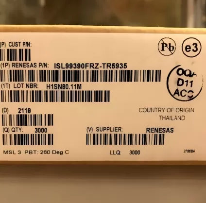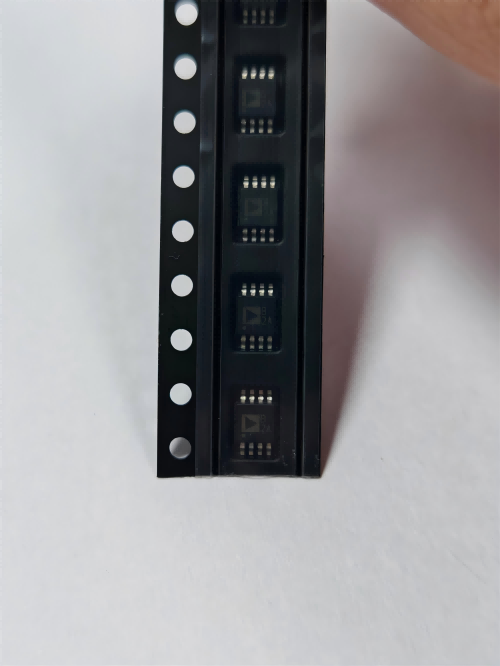

TPS62842DGRR
Brand: Texas Instruments
Texas Instruments TPS62842DGRR is a power management component designed for AI Servers & Low-Altitude Economy (Drone and UAV) and related applications. In stock at Superb Automation — request a quote for competitive pricing and fast delivery.
Product Specifications
TPS62842DGRR
Texas Instruments — Power Management & Signal Chain
Product Overview
The TPS62842DGRR from Texas Instruments is a power management / signal chain IC delivering high efficiency, precision regulation, and robust protection. Texas Instruments (TI) is a global leader in analog ICs, power management solutions, and embedded processors.
Superb Automation partners with leading brands including Qorvo, TI, ADI, XILINX, NVIDIA, Intel, ST, MACOM, Renesas, and Coilcraft to provide complete BOM and supply-chain solutions.
Key Features
- High-efficiency power conversion with low quiescent current
- Wide input voltage range with precision output regulation
- Integrated over-current, over-temperature, and short-circuit protection
- Small footprint packaging for space-constrained designs
- AEC-Q100 qualified options available for automotive applications
- Flexible sequencing and soft-start control
Key Specifications
| Input Voltage | V |
| Output Voltage | V |
| Output Current | A |
| Switching Frequency | kHz |
| Efficiency | % |
| Quiescent Current | µA |
| Topology | — |
| Package | — |
| Operating Temp | °C |
| Protection | — |
Applications
Industrial Automation
Automotive Electronics
Telecom Infrastructure
Server & Data Center Power
Medical Devices
Consumer Electronics
Request Quote — In Stock, 100% New & Original, Full Warranty
TPS62842DGRR: 750 mA step-down, 1.8 V to 6.5 V input, 60 nA quiescent, selectable output, HVSSOP-8
TPS62842DGRR is an ultra low quiescent step down converter that holds 60 nA of operating current, takes 1.8 V to 6.5 V in and delivers up to 750 mA, with the output chosen from sixteen preset values by one resistor in a HVSSOP-8 body of 8 pins. The converter runs at about 1.8 MHz and uses DCS-Control, which keeps the loop stable with small ceramic capacitors. Sixteen output voltages are selected by a resistor from the VSET pin to ground, so one part covers a family of rails and no feedback divider is needed. In 100 per cent duty mode the quiescent current rises to 120 nA, which is what the part does when the input falls close to the output.
Order code and package
| TPS62842DGRR | Active, HVSSOP (DGR) body, 8 pins, 2500 pieces on a 330 mm reel |
| TPS62842DGRR.A | Active, same body and same 2500 piece reel, material row at MSL Level-1-260C-UNLIM with a different finish |
| TPS62842DGRRG4 | Active, the same part with the green material row, 2500 pieces |
| Other bodies | the same silicon is published in a SON-8 (DLC) and a WCSP-6 (YBG) body, which are not drop in replacements for the DGR footprint |
| Temperature range | minus 40 to 125 degrees junction |
Electrical parameters that decide the application
| Input voltage | 1.8 V to 6.5 V |
| Output current | 750 mA maximum |
| Quiescent current | 60 nA operating, 120 nA in 100 per cent duty mode, 25 nA in shutdown |
| Switching frequency | about 1.8 MHz typical |
| Switch resistance in the DGR body | 460 to 630 milliohm high side at a 3.6 V input, 200 to 270 milliohm low side |
| Current limit | 1.0 A minimum, 1.2 A typical, 1.4 A maximum on the high side switch; 0.15 to 0.3 A during soft start |
| Output settings | sixteen preset voltages selected by a resistor on VSET, plus a forced PWM mode and a STOP pin for noise free measurement |
| Thermal shutdown | 160 degrees junction |
Family variants and how they differ
| TPS62842 | the VSET variant with sixteen preset outputs, described here |
| TPS62840 and TPS62841 | the same family with different preset tables, so the VSET resistor value for a given output is not interchangeable |
| Package options | SON-8, WCSP-6 and HVSSOP-8, with different thermal resistance and different board area |
| STOP pin | halts switching so a measurement can be taken without converter noise |
| MODE pin | chooses automatic power save or forced PWM at light load |
Points to check before this part goes on a BOM
Sixty nanoamps only holds if the rest of the branch holds too. The operating current of the converter itself is the smallest number on the board. A feedback resistor chain, a pull up on the enable pin and a leaky output capacitor can each be larger. This part avoids the divider by using VSET, which is the reason the number is achievable at all, and a board that adds a divider on the output defeats it.
The 750 mA rating is a switch limit, not a thermal one in this body. In the HVSSOP body the high side switch is 460 to 630 milliohm and the low side is 200 to 270 milliohm at a 3.6 V input. At 750 mA and a 50 per cent duty cycle the conduction loss is about 0.19 W before switching loss, and the eight pin body has to get rid of it through the lead frame fingers. A 1.8 V to 1.2 V rail at full current is comfortable; a 6 V to 1.8 V rail at full current makes the duty cycle short and the switching loss dominant.
The current limit sits above the rating, as it must. The high side limit is 1.0 A minimum and 1.4 A maximum while the soft start limit is 0.15 to 0.3 A. That second number is what a large output capacitor sees at power up: the part ramps the output under a much lower limit and then hands over. A board with a 100 microfarad bank therefore takes noticeably longer to reach regulation than the nominal ramp suggests.
Sixteen preset voltages are a sourcing convenience with a trap. One reel covers several rails, which cuts the number of lines on a bill of materials. The trap is that the resistor value that selects 1.8 V on this part is not the value that selects 1.8 V on a neighbouring family member, and a substitute taken from a different member produces the wrong rail with no visible sign until the board is powered. Check the table for the exact string, not for the family.
DCS-Control keeps the loop stable with small ceramic capacitors. The topology switches at about 1.8 MHz and regulates by comparing the output to an internal reference on a cycle by cycle basis, so a 10 microfarad ceramic is enough. A board that fits a 47 microfarad part to chase transient response changes the loop behaviour and can produce a slow oscillation that looks like thermal drift.
The STOP pin is a test feature that also helps in the field. Driving it stops switching so a sensitive measurement can be taken without converter noise on the rail. In a meter or a sensor front end that is worth more than the extra pin, because the alternative is a linear post regulator and its dropout. It is not a shutdown: the part resumes when the pin is released.
A 6.5 V ceiling means a 5 V bus with little margin for a surge. A 5 V rail at plus 10 per cent is 5.5 V and fine, and a single cell lithium battery is far below it. A 5 V USB input that sees a hot plug overshoot, or a 12 V bus, is outside the range. The absolute maximum in the data sheet is the number to check against a transient, and it is not much above the operating range.
Shutdown current of 25 nA is the number a battery product cares about. In a smart meter or a thermostat the converter spends most of its life either in shutdown or in a very light load state, and the difference between 25 nA and a microamp is years of shelf life. What decides it on a real board is the leakage of the output capacitor and the pull up on the enable pin, both of which sit in parallel with the part.
Two identical silicon rows differ in finish and moisture statement. The base string and the .A string ship the same die on the same 2500 piece reel with different material rows. A customer with a declared material list needs the exact string on the offer, and a distributor substitution across the two creates a documentation query even when the parts are interchangeable on the board.
What to confirm before this part goes on a purchase order
State the output voltage and the VSET resistor together, because the resistor is what sets the rail and it is not the same table across the family.
Give the load profile. A rail that sleeps at a few microamp benefits from this part and one that runs at 500 mA continuously is paying for a quiescent current it never uses, and the thermal margin in the eight pin body becomes the deciding number.
Where this order code fits
It keeps a 1.8 V or 3.3 V rail alive in a smart meter, a thermostat or a wearable that runs from a single cell or a 3.6 V lithium thionyl battery and has to survive years on the same cell. Teams comparing it with a neighbouring part start from our Power Management Cross Reference page, and teams replacing a part that has gone end of life start from the Component Lead Time Solutions page.
Questions buyers ask
Can it run from a single cell lithium battery? Yes. The input range starts at 1.8 V and a lithium cell holds above 3 V for most of its discharge, so the converter stays in normal regulation and only enters 100 per cent duty mode near the end. In that mode the quiescent current rises from 60 nA to 120 nA, which is still far below the self discharge of the cell.
Does it need a feedback divider? No. The output is selected by a resistor from VSET to ground, one of sixteen preset values. That removes the divider current, which is the point of the part, and it also removes the divider tolerance from the output accuracy.
What is the STOP pin for? It stops the converter from switching so a measurement can be taken on a quiet rail. It is used in test and measurement equipment and in metrology front ends, where converter ripple would sit inside the band being measured. The output is held by the output capacitor while it is asserted.
SUPERB holds and sources this line for production and repair demand, quoted against the exact ordering string with date codes, packing and country of origin stated on the offer. When a part is moving, the How to Verify a Drop in Replacement page sets out the checks that keep a substitute from failing on the bench.