


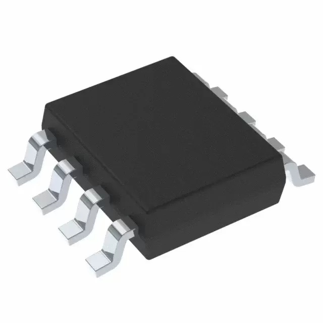

INA337AIDGKT
Brand: Texas Instruments
Texas Instruments INA337AIDGKT is a power management component designed for Industrial Automation and related applications. In stock at Superb Automation — request a quote for competitive pricing and fast delivery.
Product Specifications
INA337AIDGKT
Texas Instruments — Power Management & Signal Chain
Product Overview
The INA337AIDGKT from Texas Instruments is a power management / signal chain IC delivering high efficiency, precision regulation, and robust protection. Texas Instruments (TI) is a global leader in analog ICs, power management solutions, and embedded processors.
Superb Automation partners with leading brands including Qorvo, TI, ADI, XILINX, NVIDIA, Intel, ST, MACOM, Renesas, and Coilcraft to provide complete BOM and supply-chain solutions.
Key Features
- High-efficiency power conversion with low quiescent current
- Wide input voltage range with precision output regulation
- Integrated over-current, over-temperature, and short-circuit protection
- Small footprint packaging for space-constrained designs
- AEC-Q100 qualified options available for automotive applications
- Flexible sequencing and soft-start control
Key Specifications
| Input Voltage | V |
| Output Voltage | V |
| Output Current | A |
| Switching Frequency | kHz |
| Efficiency | % |
| Quiescent Current | µA |
| Topology | — |
| Package | — |
| Operating Temp | °C |
| Protection | — |
Applications
Industrial Automation
Automotive Electronics
Telecom Infrastructure
Server & Data Center Power
Medical Devices
Consumer Electronics
Request Quote — In Stock, 100% New & Original, Full Warranty
INA337AIDGKT: the wide input front end with the tunable filter, on a 250 piece reel
INA337AIDGKT is the precision instrumentation amplifier in the 8 pin MSOP on a 250 piece small reel, with an input window that reaches a tenth of a volt above the positive rail and 20 microvolts typical of offset. It draws 2.4 milliamps and it brings the two filter pins out, so the output corner is 1 kHz or 10 kHz depending on the capacitor fitted.
The filter is the reason to buy this part rather than a fixed bandwidth amplifier. A multiplexed channel wants the faster corner and a single channel near a switching supply wants the slower one, and the same board can be built either way. The price of the auto-corrected input stage is the internal clock, whose spurs sit at about 90 kilohertz, well above either filter corner and well inside the band of a fast converter.
INA337AIDGKT as the vendor document publishes it
| Gain | twice the ratio of the two external resistors, below 0.1 to above 10 000 |
| Offset voltage | 20 microvolts typical, 100 microvolts maximum at 5 volts |
| Offset over temperature | 140 microvolts |
| Offset drift | 0.1 microvolts per degree typical, 0.4 maximum |
| Common mode rejection | 106 dB minimum, 120 dB typical |
| Input voltage range | a quarter of a volt above the negative rail to a tenth of a volt above the positive rail |
| Input bias current | 0.2 nanoamps typical, 2 nanoamps maximum |
| Voltage noise at a gain of 100 | 33 nanovolts per root hertz at 10 Hz, 100 Hz and 1 kHz |
| Voltage noise at a gain of 10 | 120, 97 and 97 nanovolts per root hertz at 10 Hz, 100 Hz and 1 kHz |
| Low frequency noise | 0.8 microvolts peak to peak from 0.01 to 10 Hz at a gain of 100 |
| Supply range | 2.7 volts to 5.5 volts |
| Quiescent current | 2.4 milliamps typical, 3.4 milliamps maximum |
| Filter corner | 1 kHz or 10 kHz, set by an external capacitor |
| Settling to 0.1 per cent | 1.3 milliseconds at the 1 kHz filter, 160 microseconds at the 10 kHz filter |
| Overload recovery | 5 milliseconds at the 1 kHz filter |
| Clock spurs | approximately 90 kHz and its harmonics |
| Temperature range | minus 40 to plus 125 degrees |
| Body | MSOP, 8 pin, 3.00 by 3.00 millimetres |
| Vendor status | active, 250 piece small reel |
| Catalogue code | INA337AIDGKT |
| Vendor string | INA337AIDGKT |
| Marking | BIM |
| Lead finish | printed as a call to the vendor on this row |
| Moisture level | level 2, 260 degrees, one year floor life |
Twenty microvolts, and the two filter corners
The offset of INA337AIDGKT is 20 microvolts typical and 100 microvolts maximum at a 5 volt supply, with 140 microvolts over the full temperature range and a drift of 0.1 microvolts per degree typical and 0.4 maximum. The rejection is 106 dB minimum and 120 dB typical, and the bias current is 0.2 nanoamps typical.
The filter pins are the unusual part. The part carries an output filter whose corner is set by an external capacitor, and the data sheet specifies two conditions, a 1 kHz corner and a 10 kHz corner, with a settling time of 1.3 milliseconds at the first and 160 microseconds at the second. That choice is a real one for a multiplexed channel: the 1 kHz filter rejects more noise and slows the scan, and the 10 kHz filter is eight times faster and lets more of the switching residue through.
An input window that reaches past the positive rail
INA337AIDGKT is built for a common mode that sits at or above the supply. The input window runs from about a quarter of a volt above the negative rail to a tenth of a volt above the positive one, so a sensor referenced to the positive rail, a high side shunt on a 5 volt bus or a bridge whose midpoint is at the top of the rail all stay inside the window without a divider.
That is the row that separates the part from most instrumentation amplifiers, whose input range stops a volt or more inside the rails. The bias current of 0.2 nanoamps typical and 2 maximum means the window is usable with a high impedance source as well, since 2 nanoamps into 100 kilo-ohms is 200 microvolts, which is the same size as the maximum offset. A divider in front of the part would destroy the whole point: it would add a ratio error that drifts with the resistors and put the source impedance back in the signal path.
A gain below one, which most instrumentation amplifiers cannot do
The gain of INA337AIDGKT is twice the ratio of the two external resistors, and the published range runs from below 0.1 to above 10 000. A gain below one is the useful oddity: it attenuates a signal that is already large, which is what a front end on a plus or minus 10 volt transducer needs when the converter behind it accepts 2.5 volts.
That arrangement also moves the noise and the offset in the right direction, because both are referred to the input and then divided by a gain below one. The price is the resistor pair, which becomes the accuracy of the channel: at a gain of 0.08 the two resistors set a ratio, and their tracking over temperature sets the gain drift. A 0.1 per cent pair with a 25 ppm per degree window is therefore the right partner for a part whose internal network is trimmed far tighter than that.
Two point four milliamps, and the clock that comes with the loop
INA337AIDGKT draws 2.4 milliamps typical and 3.4 maximum from a 2.7 to 5.5 volt supply, which is the price of the auto-corrected input stage. The correction runs on an internal clock, and the data sheet notes spurious components at about 90 kilohertz and its harmonics, which is the row a channel with a fast converter has to check before it signs off.
In a DC channel the spurs are harmless, because the filter corner, whether 1 kHz or 10 kHz, sits far below them. In a channel that samples at 200 kilo-samples per second, the 90 kilohertz spur aliases and appears as an offset in the result, and the cure is an analogue filter ahead of the converter or a different part. The quiescent current also sets the application: 2.4 milliamps is too much for a loop powered transmitter, and it is nothing for a mains powered instrument or an automotive module.
Thirty three nanovolts, and the noise at a gain of ten
The voltage noise of INA337AIDGKT is 33 nanovolts per root hertz at 10 Hz, 100 Hz and 1 kHz when the gain is 100 with a 2 kilo-ohm and 100 kilo-ohm pair, and 120, 97 and 97 nanovolts at a gain of 10 with a 20 kilo-ohm pair. The difference between the two conditions is the resistor pair, not the amplifier: a lower gain needs larger resistors, and larger resistors carry more thermal noise.
Read that way, the noise row is a warning about the gain network rather than a specification of the part. A channel that needs 33 nanovolts at a gain of 10 has to keep the pair small enough that its own thermal noise stays under the amplifier's, and that constrains the source impedance the part can drive. The 0.01 to 10 Hz noise of 0.8 microvolts peak to peak at a gain of 100 and 4.2 microvolts at a gain of 10 follows the same pattern.
Where a rail to rail input front end belongs
INA337AIDGKT belongs on a sensor that sits at or above the supply rail, a plus or minus 10 volt industrial transducer that has to be scaled down to a converter range, a bridge whose midpoint is at the top of the rail, and a channel that needs a filter it can tune rather than one fixed inside the package.
It stops at three things. The quiescent current of 2.4 milliamps rules out a loop powered or battery instrument. The internal clock puts spurs at 90 kilohertz, which rules out an undersampled fast channel without an analogue filter. And the temperature range is industrial, with no automotive flow in this document, so an under hood module needs a different orderable code. Our amplifier cross reference page covers the precision amplifiers either side of this one, and the BOM scrubbing page covers the gain pair against the bill of materials.
The filter capacitor and the gain pair are both board level decisions. Our amplifier cross reference page covers the parts either side of this one, and the BOM scrubbing page covers the passives against the bill of materials.
Can the input sit at the positive rail? Yes, the window reaches a tenth of a volt above it, and it starts a quarter of a volt above the negative rail, so a sensor at ground needs a small negative bias or a different part.
What sets the reading speed? The filter. Settling to 0.1 per cent is 1.3 milliseconds at the 1 kHz corner and 160 microseconds at 10 kHz.