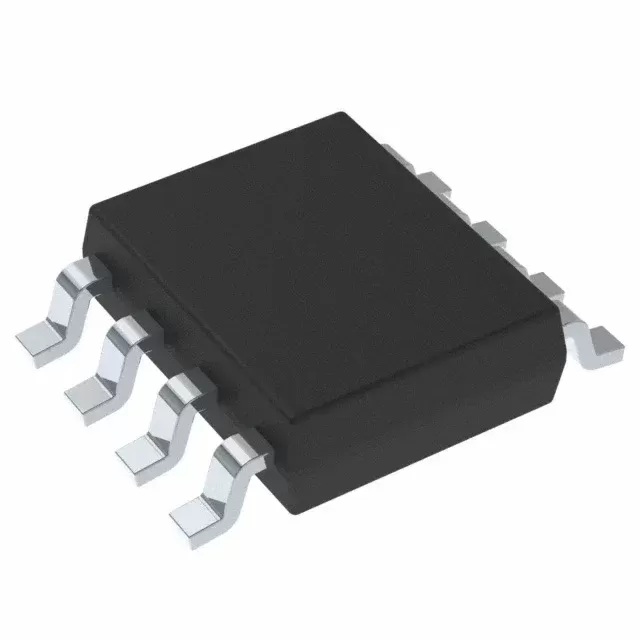
INA118UB2K5
Brand: Texas Instruments
Texas Instruments INA118UB2K5 is a power management component designed for Industrial Automation and related applications. In stock at Superb Automation — request a quote for competitive pricing and fast delivery.
Product Specifications
INA118UB2K5
Texas Instruments — Power Management & Signal Chain
Product Overview
The INA118UB2K5 from Texas Instruments is a power management / signal chain IC delivering high efficiency, precision regulation, and robust protection. Texas Instruments (TI) is a global leader in analog ICs, power management solutions, and embedded processors.
Superb Automation partners with leading brands including Qorvo, TI, ADI, XILINX, NVIDIA, Intel, ST, MACOM, Renesas, and Coilcraft to provide complete BOM and supply-chain solutions.
Key Features
- High-efficiency power conversion with low quiescent current
- Wide input voltage range with precision output regulation
- Integrated over-current, over-temperature, and short-circuit protection
- Small footprint packaging for space-constrained designs
- AEC-Q100 qualified options available for automotive applications
- Flexible sequencing and soft-start control
Key Specifications
| Input Voltage | V |
| Output Voltage | V |
| Output Current | A |
| Switching Frequency | kHz |
| Efficiency | % |
| Quiescent Current | µA |
| Topology | — |
| Package | — |
| Operating Temp | °C |
| Protection | — |
Applications
Industrial Automation
Automotive Electronics
Telecom Infrastructure
Server & Data Center Power
Medical Devices
Consumer Electronics
Request Quote — In Stock, 100% New & Original, Full Warranty
INA118UB/2K5: the B grade of a low drift instrumentation amplifier on a 2500 piece reel
The INA118 is a three op amp instrumentation amplifier with a 50 µV maximum input offset, 0.5 µV per degree maximum drift and 5 nA maximum input bias current, and the UB in this string is the B grade of the SOIC body supplied on a large reel. The reel is the part of the string that a production line actually needs, because the same die in the D package also ships in a 75 piece tube, and a tube fed line runs out mid batch. Everything else about the part follows the family: one external resistor sets any gain from 1 to 10,000, and the inputs survive 40 V of differential or common mode abuse without an external clamp.
The family carries a note at the top of the vendor document that a newer device, the INA818, is available. That note is not a discontinuation and the INA118 remains in production, but a programme starting today should look at the newer part before it commits a board, because the replacement question arrives later as a change request rather than as a circuit decision.
The INA118UB/2K5 rows as the addendum publishes them
| Part class | Precision instrumentation amplifier, three op amp |
| Vendor status | ACTIVE, production data |
| Data sheet | SBOS027C, revised September 2022 |
| Grade | B grade, the second laser trimmed bin of the family |
| Gain equation | G = 1 + 50 kΩ divided by RG |
| Gain range | 1 to 10,000 V/V with one external resistor |
| Input offset voltage | 50 µV maximum, family specification |
| Offset drift | 0.5 µV per degree maximum |
| Input bias current | 5 nA maximum |
| Common mode rejection at G = 1000 | 110 dB minimum |
| Input protection | Plus or minus 40 V without damage |
| Supply range | Plus or minus 2.25 V to plus or minus 18 V |
| Quiescent current | 350 µA |
| Body | SOIC, D outline, 8 pins |
| Carrier | 2500 pieces on a large reel for the /2K5 row |
| Tube sibling | The same D body in a 75 piece tube |
| Lead finish | Published as call TI, not fixed in the addendum |
| Moisture level | Level 3, 260 degrees, 168 hour floor life |
| Temperature range | Minus 40 to plus 85 degrees |
| Newer device note | INA818 offered by the vendor as the newer version |
Two rows above are the ones to read twice. The moisture level 3 with a 168 hour floor life is a shop floor constraint rather than a warehouse one: a reel that is opened for a partial build has to go back into dry storage or be baked before the next run, and a 2500 piece reel can easily sit open across two builds. The lead finish row says call TI, which means the finish is not the same on every shipment and has to be confirmed on the label rather than assumed from the part number.
What 0.5 µV per degree buys and what it does not
A 0.5 µV per degree drift is the reason this part is still specified in weigh scale and bridge instrumentation. Over a 25 degree excursion the offset moves 12.5 µV, which on a 10 mV full scale bridge is 0.125 per cent before the gain error is counted. A part with 5 µV per degree drift would move 125 µV over the same excursion, and at that point the drift, not the amplifier, sets the system accuracy. The number to compare against is therefore drift rather than the room temperature offset, because the offset can be trimmed at the bench and the drift cannot.
The second half of the budget is the gain resistor. The 0.5 µV per degree belongs to the amplifier, and the gain error that follows the resistor is a separate term: a 25 ppm per degree metal film resistor at a gain of 100 contributes 0.25 per cent of gain error over 100 degrees, which is larger than the amplifier drift on a 10 mV signal. A gain resistor chosen for its temperature coefficient rather than its tolerance is the cheaper way to hold a channel in specification, and it is the part of the circuit that is easiest to overlook because it costs cents.
The 40 V input protection and where it stops helping
The inputs tolerate 40 V beyond the rails without damage, which covers the ordinary fault of a transducer cable plugged in while the rack is powered. What the protection does not cover is a sustained fault at the supply pin or a reversed supply, and it does not protect the source: a 40 V fault drives current through the input protection network and into whatever is driving the amplifier, so a series resistor at the connector is still worth the board space. The protection is also a limit on the source impedance: above roughly a megohm the protection network stops being transparent and the bias current error grows with the source resistance.
At 5 nA of bias current a 1 MΩ source produces 5 mV of offset, which is a hundred times the amplifier offset and enough to break a bridge channel. The family is chosen for low bias current rather than zero bias current, and the practical rule is that the source resistance stays below about 100 kΩ, or the two input impedances are matched so the bias currents cancel. A matched pair of 100 kΩ resistors costs two parts and removes 4.9 mV of the error.
Three op amp topology, gain bandwidth and the settling question
The three op amp topology gives a differential input stage with high common mode impedance, so the common mode voltage at the source does not draw current and the common mode rejection holds to a high gain. The price is noise and headroom: the first stage carries two amplifiers in series, and the output swing of the first stage limits how much common mode the part can take before the second stage clips. On a plus or minus 15 V supply the common mode range is wide, and on a plus or minus 2.25 V supply it is narrow enough that a channel referencing ground will run out of range before the output does.
Settling is the practical bandwidth measure. A sine sweep reports the small signal bandwidth, which is generous at low gain and falls as the gain rises; a step response at the gain actually used is what decides whether the channel can follow a multiplexer. On a 100 thousand sample per second multiplexed front end the amplifier has 10 microseconds per channel, and a gain of 100 channel that needs 20 microseconds to settle to 0.01 per cent will show crosstalk between adjacent channels that looks like a converter problem and is not. The vendor publishes settling at several gains in the data sheet, and the figure for the gain in use is the one to put in the requirement.
Buying on the reel rather than in the tube
The /2K5 suffix is 2500 pieces on a large reel, and the part also exists in a 75 piece tube. For a build of 200 boards with two amplifiers each, a tube is enough and a reel is three years of stock that has to be stored at level 3. For a build of 2000 boards the reel is the only workable carrier, and the purchase order should name the carrier explicitly, because the same body is sold both ways and a distributor quoting from stock will ship whichever is on the shelf. Two identical-looking lines on a purchase order can be a tube and a reel.
The grade is the other half of the buy. The family is trimmed into two bins, the plain and the B, and this string is the B bin in the D body. A substitution to the plain grade is a change in the offset budget rather than a drop in replacement, and a customer who accepts it without checking has accepted a wider offset at the same price point. Asking for the grade and the carrier in writing, on the same line as the part number, removes both ambiguities at once. For a build that has to be auditable, our component traceability report sets out what we record against each reel, and the amplifier cross reference page lists the families we compare when a grade cannot be found.
Questions that arrive with this part number
Whether the INA818 note means the INA118 is going away is the first question, and the answer is that the vendor lists the INA118 as active production with a current addendum. The note is a recommendation, not a status change. Whether the tube and the reel are the same die is the second, and they are: the package and the grade are the same, only the carrier differs, so a line that has qualified the tube part does not need to requalify the reel part.
The third question is about the trim pins. The family does not bring out a gain trim, and the offset is trimmed at the factory; a channel that needs better than the published offset at temperature needs a different part rather than a trim pot. The fourth is about the supply: plus or minus 2.25 V is the floor, and a single 3.3 V rail is not enough, because the part needs a negative rail or a reference offset to handle a bipolar signal.