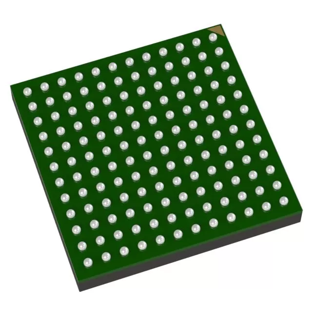

ADL9006-Die
Brand: Analog Devices
Analog Devices ADL9006-Die is a analog & mixed-signal component designed for Instrumentation and related applications. In stock at Superb Automation — request a quote for competitive pricing and fast delivery.
Product Specifications
ADL9006-Die
Analog Devices — Analog & Mixed-Signal ICs
Product Overview
The ADL9006-Die from Analog Devices is a high-performance analog / mixed-signal IC providing precision signal acquisition, conversion, and conditioning. Analog Devices (ADI) is a world leader in high-performance analog, mixed-signal, and DSP ICs for instrumentation, healthcare, automotive, and communications.
Superb Automation partners with leading brands including Qorvo, TI, ADI, XILINX, NVIDIA, Intel, ST, MACOM, Renesas, and Coilcraft to provide complete BOM and supply-chain solutions.
Key Features
- High-resolution data conversion with excellent SNR and THD
- Wide dynamic range and high linearity across operating conditions
- Integrated voltage reference with low temperature drift
- Flexible digital interface — SPI, I2C, or parallel options
- Industrial/automotive temperature range with guaranteed specs
- Low power consumption with power-down modes
Key Specifications
| Resolution | bits |
| Channels | — |
| Sample Rate | kSPS |
| Interface | — |
| Supply Voltage | V |
| Operating Temp | °C |
| Package | — |
| INL | LSB |
| SNR | dB |
| THD | dB |
Applications
Precision Instrumentation
Industrial Process Control
Medical Imaging & Diagnostics
Automotive Sensor Interfaces
Communications Infrastructure
Test & Measurement
Request Quote — In Stock, 100% New & Original, Full Warranty
ADL9006: a 2.5 dB noise figure low noise amplifier from 2 GHz to 28 GHz
The ADL9006 is a gallium arsenide pHEMT low noise amplifier for 2 GHz to 28 GHz with a 2.5 dB typical noise figure between 2 GHz and 20 GHz, 15.5 dB of gain between 6 GHz and 28 GHz, 20 dBm at one decibel compression, 20.5 dBm saturated and 26 dBm of output third order intercept, from 5 V at 53 mA. It draws a twentieth of what the power stages in this catalogue draw, and in a receive chain that is the point.
Published values
| Parameter | Value |
|---|---|
| Frequency range | 2 GHz to 28 GHz |
| Noise figure | 2.5 dB typical, 2 GHz to 20 GHz |
| Gain | 15.5 dB typical, 6 GHz to 28 GHz |
| Output power at one decibel compression | 20 dBm typical, 2 GHz to 6 GHz |
| Saturated output power | 20.5 dBm typical, 2 GHz to 6 GHz |
| Output third order intercept | 26 dBm typical, 2 GHz to 6 GHz |
| Supply | 5 V at 53 mA |
| Matching | 50 ohm input and output |
| Dissipation | 0.27 W |
| Published applications | test instrumentation, military and space, local oscillator driver |
Two and a half decibels decides the system noise figure
In a receive chain the first stage sets the noise floor, and the contribution of everything after it is divided by the gain in front of it. A 2.5 dB amplifier with 15.5 dB of gain in front of a receiver with a 10 dB noise figure gives a system figure near 2.8 dB, while a 4 dB first stage with the same gain gives about 4.3 dB. The difference between those two chains is 1.5 dB of sensitivity for the life of the product.
That is why noise figure is specified over a narrower band than gain: 2.5 dB is quoted from 2 GHz to 20 GHz, and above 20 GHz the figure rises. A system that uses the part at 26 GHz has to look at the noise figure curve at 26 GHz rather than at the headline, and the difference is a decibel or more.
Fifty three milliamps changes the thermal conversation
5 V at 53 mA is 0.27 W, against 20 dBm of saturated output, which is 0.1 W. So 0.15 W is dissipated, and the package runs cool enough that a four layer board with an ordinary pad is a complete thermal answer. This is the opposite end of the family from the power stages, where the attach and the carrier decide everything.
The small current also means the bias network is simple: no high current path, no large reservoir capacitor, and no need for a current sensing loop to hold the operating point. The gate voltage still has to be set, and the sequencing rule still applies, but the consequences of a mistake are a fraction of a watt rather than tens of watts.
An amplifier that is also a local oscillator driver
20.5 dBm of saturation with 26 dBm of intercept makes this usable as a driver for a mixer local oscillator port, where the requirement is a clean square wave of a few milliwatts to tens of milliwatts at the fundamental. In that role the noise figure matters less and the intercept and the output match matter more.
The same part serves both roles because the band is wide and the output is matched. A receiver front end uses it for the noise figure, an exciter uses it for the drive level, and the board around it is the same, which is what makes a single part number cover both in a multi channel instrument.
Where a customer needs a second position on this part, the LNA selection guide is the starting point, the RF component sourcing page sets out the checks a substitution has to pass, and RF procurement is the short lead time route we quote against.
Two questions buyers ask
Is 2.5 dB the noise figure across the whole band? No. It is the typical figure from 2 GHz to 20 GHz. Above 20 GHz the noise figure is higher, and the data sheet curves are the reference for the top of the band.
Can it drive a mixer local oscillator port? Yes. 20.5 dBm of saturation with 26 dBm of intercept is enough for many mixer local oscillator inputs, and the output is matched to 50 ohm.