

A low noise amplifier is chosen at the system level before it is chosen at the part level. The noise figure of the first stage dominates the noise figure of the receiver, so a fraction of a decibel at the input is worth more than any gain added later in the chain. The selection problem is that the same part also has to survive the blocker, fit the rail and stay stable into whatever the filter presents.
An LNA selection guide that compares only noise figure produces a receiver that is quiet on the bench and deaf next to a transmitter. The parameters have to be read together, at the bias point and the frequency the product uses.
Where LNA selection goes wrong
Noise figure at one frequency is the first mistake. The figure is quoted at a bias point, a temperature and a frequency, and a part selected on its best number can be a decibel worse at the band edge or at the rail the board actually provides. Minimum noise figure and the noise figure at the chosen bias are two different numbers, and the matching network decides which one the board sees.
Gain is the second. Gain higher than needed buys nothing and costs current, and gain flat on paper can tilt across the band. More important, gain sets the compression point of the stage that follows: a front end with high gain and a low output intercept point saturates earlier than a lower gain stage with a better intercept.
Linearity is the third. The input intercept point describes how the part behaves with two tones, the 1 dB compression point describes a single large signal, and a receiver in a dense environment needs both. A part with excellent noise figure and a poor intercept point is the classic front end that fails when a nearby transmitter keys up.
Stability and matching are the fourth. An amplifier that is stable into 50 ohms can oscillate into the reactance of a real filter, and the effect appears as a raised noise floor rather than a dead stage. Source and load impedances at the band edges are part of the selection, not a tuning detail after it.
Supply and protection are the fifth. Bias current, rail noise and decoupling decide whether the quoted noise figure is reachable, and the ESD class decides whether the part survives field service. A device that meets its numbers only with a clean lab supply has not been selected, it has been tested.
The parameters that decide an LNA choice
| Parameter | What it decides | What a weak comparison looks like |
|---|---|---|
| Noise figure at bias | The noise floor of the whole receive chain | Best case figure quoted at another bias point |
| Gain and gain flatness | The level presented to the next stage | Single frequency gain compared |
| Output intercept point | Behaviour with two strong signals present | Only the 1 dB compression point compared |
| Input compression | The largest signal before the stage desenses | Intercept quoted as a compression figure |
| Supply current and rail | Power budget and thermal rise in a sealed unit | Current compared at a different rail |
| Return loss at band edges | Whether the match holds across the band | Match checked at the centre only |
| Stability into reactance | Whether the stage oscillates with a real filter | Stability quoted into 50 ohms only |
| ESD class | Survival in handling and field service | Class not read from the datasheet |
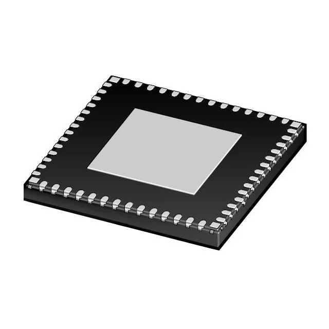
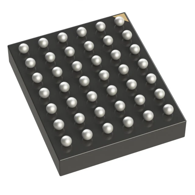
| Package and thermal path | Junction temperature at the real duty cycle | Body size compared, thermal pad ignored |
| Lifecycle and availability | Whether the part can be bought for the product life | Status not checked before release |
How SUPERB PCBA supports an LNA selection
Send the band, the noise figure the receiver has to reach, the blocker level, the rail and the current budget, the temperature and the annual quantity. The reply compares candidates against the table above and marks each difference as acceptable, needs a check, or changes the front end, with the measurement that would settle it.
The device families sit under the RF gain blocks and low noise amplifiers for receive front ends page, and the assembled front end side is covered on the LNA module PCBA page. Where the part has to be replaced rather than chosen, the equivalent numbers are collected in the amplifier cross reference.
Provenance is checked before a sample is offered. Reels are counted by X-ray, markings and date codes are inspected against maker records, and aged stock gets a solderability check before it is quoted. Verified lots carry a 730 day warranty, and a substitution enters the BOM only after written approval from your side.
Proving the front end on the board
The board decides part of the noise figure. Grounding around the package, the decoupling of the bias line and the length of the trace to the filter all move the number, and the measurement that matters is taken on the assembled board at the bias and the temperature the product uses.
SUPERB Assembly builds and tests those boards under IPC-A-610 Class 2 and Class 3 and ISO 9001, with boards supported from 500 MHz to 77 GHz, impedance held to plus or minus 5 percent and to plus or minus 2 percent where the circuit needs it, up to 68 layers, and placement down to 01005. First article inspection runs against released data, 3D SPI checks the paste before reflow, 3D AOI checks it after, X-ray runs in 2D and CT mode with voiding below 5 percent, and functional test uses a fixture approved by your team to log gain, return loss and noise figure against the limit. SUPERB Tech keeps that record with the lot number, so the next build is compared with the first one rather than with an opinion.
LNA selection questions
Is the lowest noise figure part always the right choice?
No. The lowest figure usually comes with more current or a lower intercept point, and a receiver that is quiet but compresses early fails in the field. The choice is the figure that meets the budget at the bias the board can supply.
Does a higher gain LNA improve sensitivity?
Only up to the point where the next stage stops contributing noise. Beyond that the added gain reduces the dynamic range of the chain and makes the front end easier to desense.
Can an LNA be replaced without changing the board?
It can fit the footprint, and the matching network still has to be rechecked, because the input and output impedances of the replacement determine whether the filter is presented with the load it expects.
What has to be measured after a replacement?
Gain, return loss and noise figure at the band edges, plus a two tone check for the intercept point. A bench noise figure at the centre frequency does not show what the band edges or a nearby transmitter will do.
Next step
Send the band, the noise figure target, the blocker level, the rail and current budget, the temperature and the annual quantity. You get a candidate comparison with each difference marked, the measurement needed to settle each open point, and the availability and lifecycle position of every part on the list.