
DRV8411RTER
Brand: Texas Instruments
Texas Instruments DRV8411RTER is a power management component designed for AI Servers & Low-Altitude Economy (Drone and UAV) and related applications. In stock at Superb Automation — request a quote for competitive pricing and fast delivery.
Product Specifications
DRV8411RTER
Texas Instruments — Power Management & Signal Chain
Product Overview
The DRV8411RTER from Texas Instruments is a power management / signal chain IC delivering high efficiency, precision regulation, and robust protection. Texas Instruments (TI) is a global leader in analog ICs, power management solutions, and embedded processors.
Superb Automation partners with leading brands including Qorvo, TI, ADI, XILINX, NVIDIA, Intel, ST, MACOM, Renesas, and Coilcraft to provide complete BOM and supply-chain solutions.
Key Features
- High-efficiency power conversion with low quiescent current
- Wide input voltage range with precision output regulation
- Integrated over-current, over-temperature, and short-circuit protection
- Small footprint packaging for space-constrained designs
- AEC-Q100 qualified options available for automotive applications
- Flexible sequencing and soft-start control
Key Specifications
| Input Voltage | V |
| Output Voltage | V |
| Output Current | A |
| Switching Frequency | kHz |
| Efficiency | % |
| Quiescent Current | µA |
| Topology | — |
| Package | — |
| Operating Temp | °C |
| Protection | — |
Applications
Industrial Automation
Automotive Electronics
Telecom Infrastructure
Server & Data Center Power
Medical Devices
Consumer Electronics
Request Quote — In Stock, 100% New & Original, Full Warranty
DRV8411RTER: two H bridges and a current limit in a 3 mm square
The DRV8411RTER is a dual H-bridge motor driver in a 16-pin WQFN at 3.00 mm by 3.00 mm, with a PowerPAD under it. It drives one bipolar stepper, one or two brushed DC motors, solenoids or any other inductive load from a 1.65 V to 11 V rail, and it does so with the current regulation loop already inside: an external resistor on each bridge's sense pin sets the trip point, and the driver chops the output when the current reaches it.
The output stage is four N-channel FETs per bridge with 200 mΩ on resistance high side and 200 mΩ low side at 0.2 A, which is 400 mΩ measured across one high and one low device. The peak rating is 4 A and the absolute maximum on any output is 5 A, so a small stepper at 1 A per phase runs a long way inside the numbers, while a stalled brushed motor at 3 A is the case where the current limit has to be set before the motor is connected.
The charge pump is a tripler with all capacitors integrated, which is what lets the part work down to 1.65 V and still hold the high-side FETs on at 100 percent duty. That low floor is the reason the part appears in 1.8 V logic systems and in battery products that run to the end of a single cell discharge, where a driver with a 2.7 V minimum would drop out while the microcontroller is still running.
Timing is quick enough for small motors: 100 ns rise and 50 ns fall at 5 V, 400 ns of dead time, and 600 ns from input edge to output at 1 A. Sleep current is 40 nA at 5 V and 25 C, which is low enough that a battery toy or a smart lock can leave the driver connected and rely on the microcontroller to wake it through nSLEEP.
Key data for the DRV8411RTER
| Operating range | 1.65 V to 11 V on VM, tripler charge pump integrated |
| Outputs | Two H bridges, four N-channel FETs each, 200 mOhm high side and 200 mOhm low side at 0.2 A |
| Current | 4 A peak rating, 5 A absolute maximum on any output |
| Current regulation | External sense resistor per bridge, trip window 180 mV to 230 mV around a 200 mV typical |
| Timing | 100 ns rise, 50 ns fall at 5 V, 400 ns dead time, 600 ns propagation at 1 A |
| Logic | 1.8 V, 3.3 V and 5.0 V inputs |
| Sleep current | 40 nA at 5 V and 25 C junction |
| Undervoltage | 1.6 V rising and 1.3 V falling, 100 mV of hysteresis |
| Protection | Overcurrent with auto retry, thermal shutdown, nFAULT output |
Body, packing and marking data
| Body | 16-pin WQFN, the RTE outline, 3.00 mm by 3.00 mm with a PowerPAD |
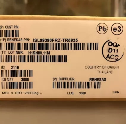
| Carrier | 5000 pieces on a 330 mm large tape and reel |
| Finish | NIPDAU lead finish, moisture level 1, 260 C peak reflow, unlimited floor life |
| Temperature | Minus 40 C to plus 125 C operating |
| Marking | 8411 on the body, lot and date code on the reel label |
Reading the code before you buy it
DRV8411 is the circuit, RTE is the 16-pin 3 mm by 3 mm WQFN, and the trailing R is the large reel. The same circuit is also published as DRV8411PWPR in a 16-pin HTSSOP at 5.00 mm by 6.40 mm, which is the body to pick when the board is hand assembled or when the thermal path has to go through the package rather than the pad. The two bodies are not interchangeable, and the reel counts differ: 5000 for the QFN, 2500 or so for the HTSSOP depending on the row.
The DRV8411A is a separate order code and not a revision. The vendor document lists both in the pin to pin table, with the same 400 mΩ per bridge, which means the A part is a different die in the same footprint rather than a newer version of this one. A buyer who receives an A when the drawing says DRV8411 should treat it as a substitution that needs an approval, not as the same part with a suffix.
There is also a family ladder behind this part that matters for second sourcing. The 16-pin footprint is shared with DRV8833 at 360 mΩ per bridge, DRV8833C at 1735 mΩ, DRV8847 at 1000 mΩ, DRV8410 at 800 mΩ and the DRV8411A at 400 mΩ, so a drive that needs less current can drop down that list without touching the board, and a drive that needs more can move up it.
Where the DRV8411RTER fits
POS printers, video security cameras with pan and tilt, office automation and gaming machines all run small brushed motors from 5 V or 12 V, and this driver covers two of them per package with a current limit that protects the motor winding when the mechanism jams. Smart locks and battery powered toys use the 40 nA sleep current and the 1.65 V floor, because the pack voltage falls and the driver has to keep working after the microcontroller has already browned out a lesser part.
Steppers in instrumentation use one bridge per winding and the current regulation to hold a constant phase current as the supply moves. The trip point is set by the sense resistor, so a 0.5 Ω resistor gives a 400 mV drop at 0.8 A and the 200 mV reference limits the current to about 0.4 A per phase, which is the arithmetic that has to be done before the resistor is chosen. Our how to verify a drop in replacement page walks through the same check when a DRV8833 is replaced by this part.
Robotics end effectors and laboratory fixtures use the parallel bridge mode, where the two bridges are tied together to halve the on resistance and drive one larger motor. That mode is a wiring change rather than a part change, and it is the reason a single order code covers a 1 A gripper and a 2 A linear actuator on the same product family.
Questions we get on this code
How is the current limit calculated? The trip voltage is 200 mV typical with a 180 mV to 230 mV window, and the current is that voltage divided by the sense resistance. A 0.2 Ω resistor gives about 1 A, and because the window is plus or minus 15 percent, the same resistor can trip anywhere between 0.9 A and 1.15 A. A board that needs a tight limit has to leave that spread in the margin.
Can the outputs be paralleled for more current? Yes, the vendor describes a parallel bridge mode that ties the two bridges together and halves the on resistance, which turns two 400 mΩ bridges into one 200 mΩ bridge. What it does not do is double the current rating of the package, because the thermal path is the same pad in the same 3 mm body.
Does the part need external flyback diodes? No. The FETs have body diodes and the driver handles the inductive recirculation internally, which is why a solenoid can be connected directly. What the board does need is a bulk capacitor close to VM, because the recirculation current has to come from somewhere and a long supply lead will ring.
What happens at 12 V? The operating maximum is 11 V and there is no 12 V rating, so a nominal 12 V rail that sits at 12.6 V when the battery is full is outside the window. A 12 V system needs a driver rated above it, and a 5 V system with a 1.65 V floor is the sweet spot for this part.
Is the QFN reel always 5000 pieces? The published row is 5000 on a large reel, which is a lot for a product that ships hundreds. The HTSSOP body is published at a smaller count, and our how to reduce component cost page covers how to decide between the two when the reel size is the bigger number on the quote.