
DRV411AIRGPR
Brand: Texas Instruments
Texas Instruments DRV411AIRGPR is a power management component designed for AI Servers & Low-Altitude Economy (Drone and UAV) and related applications. In stock at Superb Automation — request a quote for competitive pricing and fast delivery.
Product Specifications
DRV411AIRGPR
Texas Instruments — Power Management & Signal Chain
Product Overview
The DRV411AIRGPR from Texas Instruments is a power management / signal chain IC delivering high efficiency, precision regulation, and robust protection. Texas Instruments (TI) is a global leader in analog ICs, power management solutions, and embedded processors.
Superb Automation partners with leading brands including Qorvo, TI, ADI, XILINX, NVIDIA, Intel, ST, MACOM, Renesas, and Coilcraft to provide complete BOM and supply-chain solutions.
Key Features
- High-efficiency power conversion with low quiescent current
- Wide input voltage range with precision output regulation
- Integrated over-current, over-temperature, and short-circuit protection
- Small footprint packaging for space-constrained designs
- AEC-Q100 qualified options available for automotive applications
- Flexible sequencing and soft-start control
Key Specifications
| Input Voltage | V |
| Output Voltage | V |
| Output Current | A |
| Switching Frequency | kHz |
| Efficiency | % |
| Quiescent Current | µA |
| Topology | — |
| Package | — |
| Operating Temp | °C |
| Protection | — |
Applications
Industrial Automation
Automotive Electronics
Telecom Infrastructure
Server & Data Center Power
Medical Devices
Consumer Electronics
Request Quote — In Stock, 100% New & Original, Full Warranty
DRV411AIRGPR: The Front End That Turns an InSb Hall Element Into a Closed Loop Current Sensor
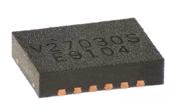
DRV411AIRGPR is a sensor signal conditioning circuit for closed loop magnetic current sensors in a QFN (RGP) body of 20 pins. It excites an indium antimonide Hall element with a spinning current, amplifies the result with a differential stage whose offset is 100 uV maximum and whose drift is 2 uV per degree, and drives the compensation coil of a closed loop current sensor with a 250 mA H bridge. Spinning the excitation reverses the Hall connections at a chopping rate, which cancels the element offset and its drift and moves the 1/f noise out of the signal band, so a module built around it measures a DC current with the stability of an AC measurement.
Order code and package
| Ordering string | DRV411AIRGPR |
| Family document | DRV411, SBOS693B, revised December 2013 |
| Package | QFN (RGP), 20 pins, 4.00 mm by 4.00 mm with a thermal pad |
| Reel and packing | 3000 pieces on a large reel |
| Lead finish and moisture | NIPDAU, level 3 at 260 C, 168 hour floor life |
| Temperature range | minus 40 to plus 125 degrees |
| Body marking | DRV411 |
| Second body | TSSOP-20 with a PowerPAD, order code DRV411AIPWPR |
| Obsolete row in the same family | DRV411AIPWP in a tube, marked Obsolete in the addendum |
| Hall element type | InSb, symmetric, for example the AKM HW-322 or HW-302 |
| Output reference | Pin selectable 2.5 V, 1.65 V or ratiometric to the supply |
| Error reporting | Overrange flag on an open drain output |
Electrical parameters that decide the application
| Supply range | 2.7 to 5.5 V |
| Supply current | About 6 mA with the coil drive at zero |
| Coil driver | 250 mA H bridge, which roughly doubles the measurement range of a single ended drive |
| Differential amplifier offset | 100 uV maximum |
| Offset drift | 2 uV per degree maximum |
| System bandwidth | 200 kHz |
| Reference accuracy | 0.2 per cent maximum |
| Reference drift | 50 ppm per degree maximum |
| Reference values | 2.5 V, 1.65 V or ratiometric, chosen by two pins |
| Front end zero | A zero at 7.2 kHz in one of the gain settings, for the spinning ripple |
| Overrange delay | 2.5 to 3.5 us after a 1 V step |
| Input protection | The amplifier inputs must be limited to 5 mA, they are not protected internally |
Family variants and how they differ
| DRV411AIPWPR | The TSSOP-20 body, 2000 pieces on a large reel |
| DRV411AIPWP | The tube row, printed as Obsolete in the addendum |
| DRV411AIRGPR | This part, the 4 mm QFN with the same die |
| DRV401 | An earlier and simpler version of the same function |
| DRV421 | A later integrated fluxgate sensor with the coil driver inside |
| DRV425 | A complete fluxgate field sensor, not a front end for an external element |
Points to check before this part goes on a BOM
Spinning current is the whole idea and it is worth understanding before choosing the part. The Hall element produces an offset voltage that drifts with temperature and a 1/f noise corner that sits inside the band of a DC measurement. Reversing the excitation and the sense connections at a few tens of kilohertz converts that offset into a square wave at the chopping frequency, which the following stage removes with a filter, leaving the wanted signal.
The 250 mA H bridge is what makes a closed loop module possible in a small case. A closed loop sensor drives a compensation coil until the flux in the core is zero, and the coil needs tens of milliamps for a few amps of measured current. Driving the coil from a single ended amplifier halves the available range, so the bridge roughly doubles it at the same supply.
The reference accuracy sets the module accuracy. A 0.2 per cent reference with 50 ppm per degree of drift is what allows a current sensor to hold 0.5 per cent over a wide temperature range without a calibration step at every unit. The pin selectable 2.5 V, 1.65 V and ratiometric modes exist because a 3.3 V ADC wants a different reference from a 5 V one.
The amplifier inputs are not protected against overvoltage and have to be limited to 5 mA. That is a real constraint on a current sensor that may see a fault current far above its range, because the coil drive saturates and the element can be driven hard. Series resistors at the element are part of the circuit, and their value is set by the maximum fault the module has to survive.
The overrange flag is the only diagnostic, and it is an open drain output with a delay of 2.5 to 3.5 us. It tells the controller that the measured current has left the linear range, which in a closed loop sensor means the core is saturating and the reading is no longer trustworthy. A product that trips a breaker on this flag needs the delay in its debounce calculation.
Where this front end is used
A panel meter, a servo drive, a battery test rig or an electric vehicle charger needs an isolated or a high current measurement with better than 1 per cent accuracy over temperature. A closed loop Hall module with this front end gives that, with a bandwidth of 200 kHz, which is enough to see a switching ripple and to protect a bridge from a short circuit.
A medical or laboratory instrument uses the same block where the offset drift of an open loop sensor would show up as a slowly wandering zero. The spinning excitation removes the drift at the source rather than calibrating it out, which is why the part is specified with microvolt level offset and microvolt per degree drift rather than with a trim procedure.
What has to be checked before the part goes into a module
The Hall element has to be a symmetric InSb type with the connections the part expects, for example the AKM HW-322 or HW-302 named in the document. A different element, or an asymmetric one, defeats the spinning scheme because the offset does not cancel when the connections are reversed, and the module still works but with the drift the part was chosen to remove.
The second check is the coil and its drive. The 250 mA bridge has a voltage drop and a thermal rise, and the coil resistance sets the current the bridge can reach at the supply. A coil with too much resistance saturates the drive before the rated current, which shows up as a module that reads correctly at half scale and clips above it.
Where this order code fits
The part suits a closed loop Hall current sensor module that has to hold its accuracy over temperature, in a case small enough for a 4 mm square body. Teams comparing it with a neighbouring part start from our Power Management Cross Reference page, and teams replacing a part that has gone end of life start from the Pin to Pin Cross Reference page.
Questions buyers ask
Is this a current sensor on its own? No. It is the front end for a module built around an external InSb Hall element and a compensation coil. It excites the element, amplifies the difference and drives the coil, and the module accuracy depends on the core and the coil as much as on the chip.
How does it remove the offset drift? By reversing the Hall element excitation and the sense connections at a chopping rate, so the offset becomes an alternating signal that the following stage filters out. The wanted signal does not reverse, so it survives the filter.
Which reference should I select? 2.5 V for a 5 V system, 1.65 V for a 3.3 V one, or the ratiometric mode when the ADC and the sensor share a supply and the reading should track it. The choice is made by two pins and costs 0.2 per cent of reference accuracy either way.
SUPERB holds and sources this line for production and repair demand, quoted against the exact ordering string with date codes, packing and country of origin stated on the offer. When a part is moving, the Obsolete Part Cross Reference Hub page sets out the checks that keep a substitute from failing on the bench.