


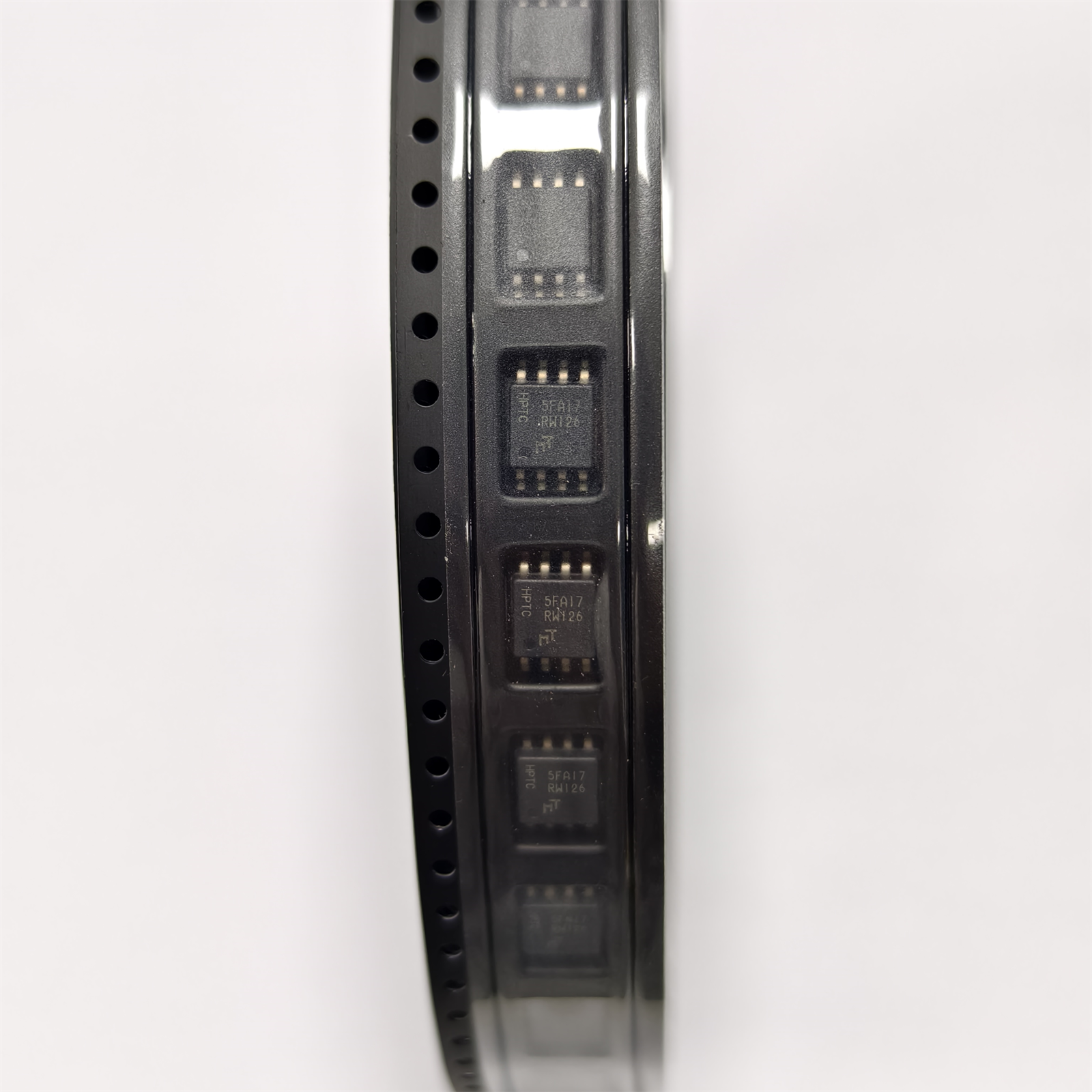
MT25QL128ABA1ESE-0SIT
The MT25QL128ABA1ESE-0SIT is a 128 M-bit (16 MB) serial NOR Flash memory device from Micron Technology's MT25Q family. Supporting Extended SPI, Dual SPI, and Quad SPI interfaces at up to 133 MHz, it delivers fast execute-in-place (XiP) performance for boot code, FPGA configuration bitstreams, and embedded firmware — all from a standard 8-pin SOP2 (wide SOIC-8) package operating across the full −40°C to +85°C industrial temperature range.
Product Specifications
MT25QL128ABA1ESE-0SIT — 128Mb Serial NOR Flash Memory by Micron Technology
The MT25QL128ABA1ESE-0SIT is a 128 M-bit (16 MB) serial NOR Flash memory device from Micron Technology's MT25Q family. Supporting Extended SPI, Dual SPI, and Quad SPI interfaces at up to 133 MHz, it delivers fast execute-in-place (XiP) performance for boot code, FPGA configuration bitstreams, and embedded firmware — all from a standard 8-pin SOP2 (wide SOIC-8) package operating across the full −40°C to +85°C industrial temperature range.
Part Number Decoded — Field by Field
| Field | Value | Meaning |
|---|---|---|
| MT25Q | Product Prefix | Micron Serial NOR Flash — "Q" denotes Quad SPI capable |
| L | Voltage | 3 V (2.7V–3.6V). "U" = 1.8V variant (MT25QU…) |
| 128 | Density | 128 M-bit = 16 MB |
| A | Technology Node | First-generation 45 nm MirrorBit® process |
| B | Feature Set | Extended SPI + Dual + Quad I/O, uniform sector architecture |
| A | Bus Width Option | ×1, ×2, ×4 (all three bus widths supported) |
| 1 | Die Count | Single die (monolithic 128 Mb) |
| ESE | Package + Die | E-die, SOP2-8 (8-pin, 208 mil wide body) |
| -0S | Speed Grade | 133 MHz (Quad SPI), 66 MHz (Single/Dual SPI) |
| IT | Temperature | Industrial: −40°C to +85°C |
Quick Specifications
| Parameter | Value |
|---|---|
| Manufacturer | Micron Technology |
| Part Number | MT25QL128ABA1ESE-0SIT |
| Mouser # | 340-224871-TRAY |
| Family | MT25Q — Serial NOR Flash with Quad SPI |
| Technology | 45 nm MirrorBit® NOR Flash |
| Density | 128 M-bit = 16 MB |
| Organization | 16M × 8-bit or 32M × 4-bit |
| Sector Size | 4 KB Uniform Subsector / 32 KB / 64 KB Sector Erase |
| Interface | Extended SPI / Dual SPI / Quad SPI (Quad I/O) |
| Max Clock (Quad SPI) | 133 MHz |
| Max Clock (Single/Dual SPI) | 66 MHz |
| Access Time | 6 ns (Clock-to-Data Output) |
| Supply Voltage | 2.7 V to 3.6 V |
| Active Read Current | 35 mA (Max, Quad SPI @ 133 MHz) |
| Standby Current | ~50 µA (Typical) |
| Deep Power-Down | ~5 µA (Typical) |
| Program/Erase Cycles | 100,000 Cycles per Sector (Minimum) |
| Data Retention | 20+ Years |
| Program Buffer Size | 256 Bytes per Page |
| Page Program Time | ~0.4 ms (Typical, 256 Bytes) |
| Sector Erase (4 KB) Time | ~45 ms (Typical) |
| Block Erase (32 KB) Time | ~120 ms (Typical) |
| Block Erase (64 KB) Time | ~150 ms (Typical) |
| Die Erase Time | ~40 s (Typical, 128 M-bit) |
| OTP Area | 64 Bytes, One-Time Programmable |
| Security Features | Block Protection (BP0–BP3), Status Register Lock, Volatile/Non-Volatile Configuration |
| Package | SOP2-8 (Wide SOIC-8, 208 mil body width) |
| Pin Pitch | 1.27 mm |
| Operating Temperature | −40°C to +85°C (Industrial, "IT" suffix) |
| RoHS | Compliant |
| Mouser Packaging | Tray (340-224871-TRAY); Reel variant: 340-224871-REEL |
Product Overview
The MT25QL128ABA1ESE-0SIT is Micron's flagship 128 M-bit (16 MB) serial NOR Flash for embedded boot and code-storage applications. Built on Micron's 45 nm MirrorBit® process technology, it stores 2 bits per cell — twice the density of traditional floating-gate NOR per silicon area — delivering higher capacity at a competitive cost per bit while retaining NOR's advantages: fast random read access, deterministic XiP performance, and per-bit addressability.
With 16 MB of contiguous addressable memory in a single-die 8-pin SOP2 package, the MT25QL128ABA1ESE-0SIT is the natural choice when 64 Mb parts (8 MB) are too small and discrete NAND would introduce unwanted complexity (bad-block management, wear leveling, ECC requirements). It sits in the sweet spot for modern embedded Linux boot flows: large enough to hold U-Boot SPL + U-Boot proper + a recovery kernel image + a device-tree blob, with room to spare for a manufacturing log and OTA backup partition.
The Quad SPI interface delivers 66 MB/s effective throughput (133 MHz × 4 bits ÷ 8) — fast enough for direct XiP code execution on ARM Cortex-A processors up to ~600 MHz without stalling the instruction pipeline.
Key Features & Benefits
128 M-bit (16 MB) — 4× the Density of Entry-Level Boot Flash
At 16 MB, the MT25QL128 provides four times the capacity of common 32 M-bit boot Flash devices (W25Q32JV, MX25L32) — enabling more ambitious firmware strategies:
Dual-bank firmware updates: Store two complete 8 MB firmware images for A/B OTA updates. If the update fails, the bootloader falls back to the known-good image automatically.
FPGA configuration: Hold multiple compressed FPGA bitstreams for Xilinx 7-series, Zynq, or Intel MAX 10 FPGAs. A 16 MB device stores multiple complete configurations for multi-mode operation.
Embedded Linux boot chain: U-Boot SPL (~64 KB) + U-Boot (~1 MB) + Linux kernel (~6 MB) + Device Tree + Initramfs = easily fits within 8 MB, leaving 8 MB for user data or a second partition.
Quad SPI at 133 MHz — XiP Without DRAM
In Quad SPI mode at 133 MHz, the MT25QL128 achieves an effective read throughput of 66 MB/s. For read-heavy workloads like boot code execution and FPGA configuration, this eliminates the need for code-shadowing DRAM — reducing BOM cost, board area, and power consumption. The 6 ns clock-to-data access time ensures deterministic random read latency that DRAM-based systems (which must account for refresh and bank collisions) cannot match.
Industrial Temperature: −40°C to +85°C
The "-0SIT" suffix guarantees operability across the full industrial temperature range — critical for outdoor equipment, automotive-adjacent ECUs, and factory-floor automation where ambient temperatures swing from freezing winter mornings to sweltering summer afternoons inside an unventilated enclosure.
Uniform 4 KB Subsector Erase — Fine-Grained FTL Support
Unlike some legacy NOR architectures with fixed 64 KB erase blocks, the MT25Q family supports 4 KB subsector erase, giving flash translation layers (FTLs) and filesystems (LittleFS, SPIFFS) fine-grained control over wear leveling. This extends effective device lifetime in data-logging applications where small records are frequently updated.
Extended SPI Protocol — DTR and XIP Modes
Beyond basic Quad SPI, the MT25Q supports Double Transfer Rate (DTR) mode where both address and data are latched on both edges of the clock, doubling command throughput. Combined with XiP (Execute-in-Place) mode — which skips the read-opcode byte on sequential reads using a dedicated configuration bit — the effective random-read latency drops to just the address phase + 6 ns access time.
Hardware Write Protection
Block Protect Bits (BP0–BP3): Software-configurable, hardware-enforced protection of the top or bottom portion of memory — essential for write-protecting the boot sector while allowing application data writes.
Status Register Lock (SRWD bit + WP# pin): When WP# is held low and SRWD is set, the entire Status Register (including BP bits) is frozen — immune to both software commands and spurious writes from a crashed MCU.
Volatile/Non-Volatile Configuration: Protection settings can be made power-cycle-persistent (non-volatile) or session-only (volatile) — useful for development and manufacturing flows.
Target Applications
Embedded Boot Flash
Primary boot device for ARM Cortex-A SoCs (NXP i.MX6/8, TI AM335x/AM62x, STM32MP1), RISC-V processors, and FPGA SoCs (Xilinx Zynq, Intel Agilex). The deterministic XiP performance eliminates DRAM from the critical boot path, reducing boot time and power-on latency.
FPGA Configuration Storage
Store one or more FPGA configuration bitstreams for Xilinx (SPI ×1/×2/×4 modes), Intel (AS ×1/×4), and Lattice (SPI Master) FPGAs. At 16 MB, the MT25QL128 holds multiple complete configurations — enabling runtime FPGA reconfiguration without external storage.
Automotive & Industrial ECUs
Engine control units, body control modules, and industrial PLCs use NOR Flash for guaranteed boot reliability. The −40°C to +85°C industrial rating covers under-hood and outdoor enclosure deployments. The 20-year data retention exceeds typical automotive module lifecycles.
IoT Gateways & Edge Nodes
LoRaWAN and cellular IoT gateways running embedded Linux store the full boot chain (SPL → U-Boot → kernel → DT) in a single MT25QL128. The 16 MB capacity also accommodates OTA A/B update partitions for zero-downtime firmware rollouts.
Networking Equipment
Enterprise switches, Wi-Fi access points, and SD-WAN appliances use serial NOR for boot firmware storage. The fast Quad SPI read speed and deterministic latency are well suited for boot-from-Flash architectures in networking ASICs and SoCs.
Medical & Safety-Critical Devices
Infusion pumps, patient monitors, and diagnostic equipment where boot integrity is safety-critical. The hardware block protection and non-volatile configuration registers prevent accidental or malicious firmware corruption — a key requirement for IEC 62304-compliant medical software.
Voltage Variant Comparison: QL (3V) vs QU (1.8V)
| Feature | MT25QL128ABA1ESE-0SIT (3V) | MT25QU128ABA1ESE-0SIT (1.8V) |
|---|---|---|
| Supply Voltage | 2.7V – 3.6V | 1.7V – 2.0V |
| Quad SPI Clock (Max) | 133 MHz | 133 MHz |
| Active Read Current | ~35 mA | ~20 mA |
| Density / Organization | 128 Mb / 16M×8 | 128 Mb / 16M×8 |
| Package | SOP2-8 (208 mil) | SOP2-8 (208 mil) |
| Logic Compatibility | 3.3V MCU I/O (STM32, NXP, TI) | 1.8V SoC I/O (Zynq, modern ARM) |
| Best For | Legacy 3.3V designs, industrial | Low-power 1.8V mobile/embedded SoC |
Selection guide: Choose QL (3V) when the host MCU/SoC uses 3.3V I/O — this covers the vast majority of STM32, NXP Kinetis/LPC, and TI Sitara designs. Choose QU (1.8V) for modern low-voltage platforms (Zynq UltraScale+ PS, NXP i.MX8M at 1.8V I/O) where 3.3V Flash would require level shifters. The two variants are NOT pin-compatible — order the correct voltage variant for your design.
MT25QL128 vs Competing 128 Mb Serial NOR Flash
| Feature | MT25QL128ABA1ESE (Micron) | W25Q128JVSIQ (Winbond) | IS25LP128-JBLE (ISSI) | S25FL128LAGMFI (Infineon/Cypress) |
|---|---|---|---|---|
| Density | 128 Mb (16 MB) | 128 Mb (16 MB) | 128 Mb (16 MB) | 128 Mb (16 MB) |
| Max Clock (Quad SPI) | 133 MHz | 133 MHz | 133 MHz | 133 MHz |
| Interface | Ext/SPI/Dual/Quad+DTR | SPI/Dual/Quad | SPI/Dual/Quad | SPI/Dual/Quad |
| Voltage | 2.7V–3.6V | 2.7V–3.6V | 2.7V–3.6V | 2.7V–3.6V |
| Active Read Current | 35 mA | 25 mA | 25 mA | 30 mA |
| Standby Current | ~50 µA | ~10 µA | ~15 µA | ~20 µA |
| Sector Erase (4 KB) | ✓ | ✓ | ✓ | ✓ |
| P/E Cycles | 100,000 | 100,000 | 100,000 | 100,000 |
| Data Retention | 20+ Years | 20+ Years | 20+ Years | 20+ Years |
| DTR Mode | ✓ (Double Transfer Rate) | — | — | — |
| XiP Mode | ✓ | ✓ | ✓ | ✓ |
| OTP Area | 64 Bytes | 3×256 Bytes | 4 K-bit | 1 K-bit |
| Package | SOP2-8 (208 mil) | SOIC-8 (208 mil) | SOP-8 (200 mil) | SOIC-8 (208 mil) |
| Temperature | −40 ~ +85°C | −40 ~ +85°C | −40 ~ +85°C | −40 ~ +85°C |
| Process Tech | 45 nm MirrorBit® (2 bit/cell) | Floating Gate | Floating Gate | 65 nm MirrorBit® |
Bottom line: The MT25QL128 offers DTR (Double Transfer Rate) mode as a unique differentiator — it is the only 128 Mb NOR Flash in this comparison that supports address/data latching on both clock edges, effectively doubling command throughput. Winbond's W25Q128JV has the lowest standby current. For designs where DTR mode is not needed, the Winbond and ISSI parts are strong second-source candidates. Infineon's S25FL128L shares the same MirrorBit® lineage (from Cypress/Spansion heritage) and is the closest architectural match for drop-in replacement consideration.
Frequently Asked Questions
What is the difference between MT25QL128ABA1ESE-0SIT and MT25QL128ABA1EW7-0SIT?
The "ESE" variant uses the SOP2-8 package (8-pin wide SOIC, 208 mil). The "EW7" variant uses the WLCSP (Wafer-Level Chip Scale Package) — a much smaller, ball-grid footprint intended for space-constrained designs. The silicon die (E-die) is identical between both variants. Choose ESE for standard PCB assembly with 1.27 mm pitch; choose EW7 only when board area is severely constrained and WLCSP assembly capability is available.
Can I use the MT25QL128 as a drop-in replacement for the Winbond W25Q128JV?
Not electrically drop-in — despite sharing the same 8-pin SOP2 package, the command sets differ. The MT25Q uses Micron's Extended SPI protocol which adds opcodes (DTR commands, 4-byte addressing modes) not present in Winbond's command set. A firmware-level abstraction layer (flash driver) is required to handle the command-set differences. If a drop-in second source is mission-critical, pre-qualify both parts in your firmware and test command-set compatibility thoroughly.
Is the MT25QL128 affected by the 2026 NOR Flash shortage?
Yes. As of June 2026, the MT25Q family is experiencing 20+ week lead times industry-wide. SUPERB Automation works with trusted Micron distribution to secure competitive allocation and can advise on alternative parts (W25Q128JVSIQ, IS25LP128-JBLE, S25FL128LAGMFI) if immediate availability is required. Contact pcba@superb-tech.com for current lead time and stock status.
What is the difference between MT25QL128 and MT25QU128?
The QL variant operates at 3V (2.7V–3.6V). The QU variant operates at 1.8V (1.7V–2.0V). They are NOT pin-compatible and must not be swapped on the same PCB — order the variant matching your host SoC I/O voltage. Using 1.8V Flash on a 3.3V bus will damage the device; using 3V Flash on a 1.8V bus will result in unreliable reads due to insufficient VIH margin.
What is MirrorBit® technology and how does it differ from traditional NOR Flash?
MirrorBit® stores 2 bits per memory cell by using physically separated charge-trapping regions on either side of the cell — unlike floating-gate NOR which stores 1 bit per cell. This doubles density per silicon area without requiring multi-level cell (MLC) voltage-sensing circuits (which add read latency). The result: NOR Flash capacity approaching NAND density, but with the fast random access and bit-level addressability that NOR provides. MirrorBit® is the technology behind Micron's (and formerly Numonyx/Intel's) 65 nm and 45 nm NOR Flash families.
What is the minimum order quantity (MOQ)?
Contact SUPERB Automation for a tailored quote. We support prototype tray quantities through full production volumes. Send your BOM to pcba@superb-tech.com — we quote within hours.
Ordering Information
| Orderable Part Number | Mouser # | Package | Packaging | Temperature |
|---|---|---|---|---|
| MT25QL128ABA1ESE-0SIT | 340-224871-TRAY | SOP2-8 | Tray | −40°C to +85°C |
| MT25QL128ABA1ESE-0SIT TR | 340-224871-REEL | SOP2-8 | Tape & Reel | −40°C to +85°C |
| MT25QU128ABA1ESE-0SIT | — | SOP2-8 | Tray | −40°C to +85°C |
| MT25QL128ABA1EW7-0SIT | — | WLCSP | Tray | −40°C to +85°C |
Design Resources
Datasheet: Micron MT25QL128ABA — Complete datasheet covering all variants, AC/DC characteristics, timing diagrams, and command set
Application Note: Micron TN-25-05 — "Migration Guide from N25Q to MT25Q" (compatibility with legacy Numonyx N25Q SPI Flash)
IBIS Model: Available from Micron for SI simulation at 133 MHz
Footprint / Symbol: Available from SnapEDA, Ultra Librarian for Altium, Eagle, KiCad, OrCAD — SOP2-8 Wide (8-SOIC, 208 mil body)
Second-Source Guide: Contact SUPERB for a cross-reference of pin- and command-set-compatible alternatives (IS25LP128, W25Q128JV, S25FL128L)
Request a Quote
SUPERB Automation supplies genuine Micron MT25QL128ABA1ESE-0SIT serial NOR Flash with full traceability. Whether you need tray quantities for prototype bring-up or tape-and-reel for high-volume production, we deliver — with transparent lead-time visibility during the ongoing NOR Flash allocation period.
Send your BOM or inquiry to pcba@superb-tech.com — we quote within hours. Include your annual volume forecast for allocation planning.
SUPERB Automation — We Make It Real. Since 2000.