

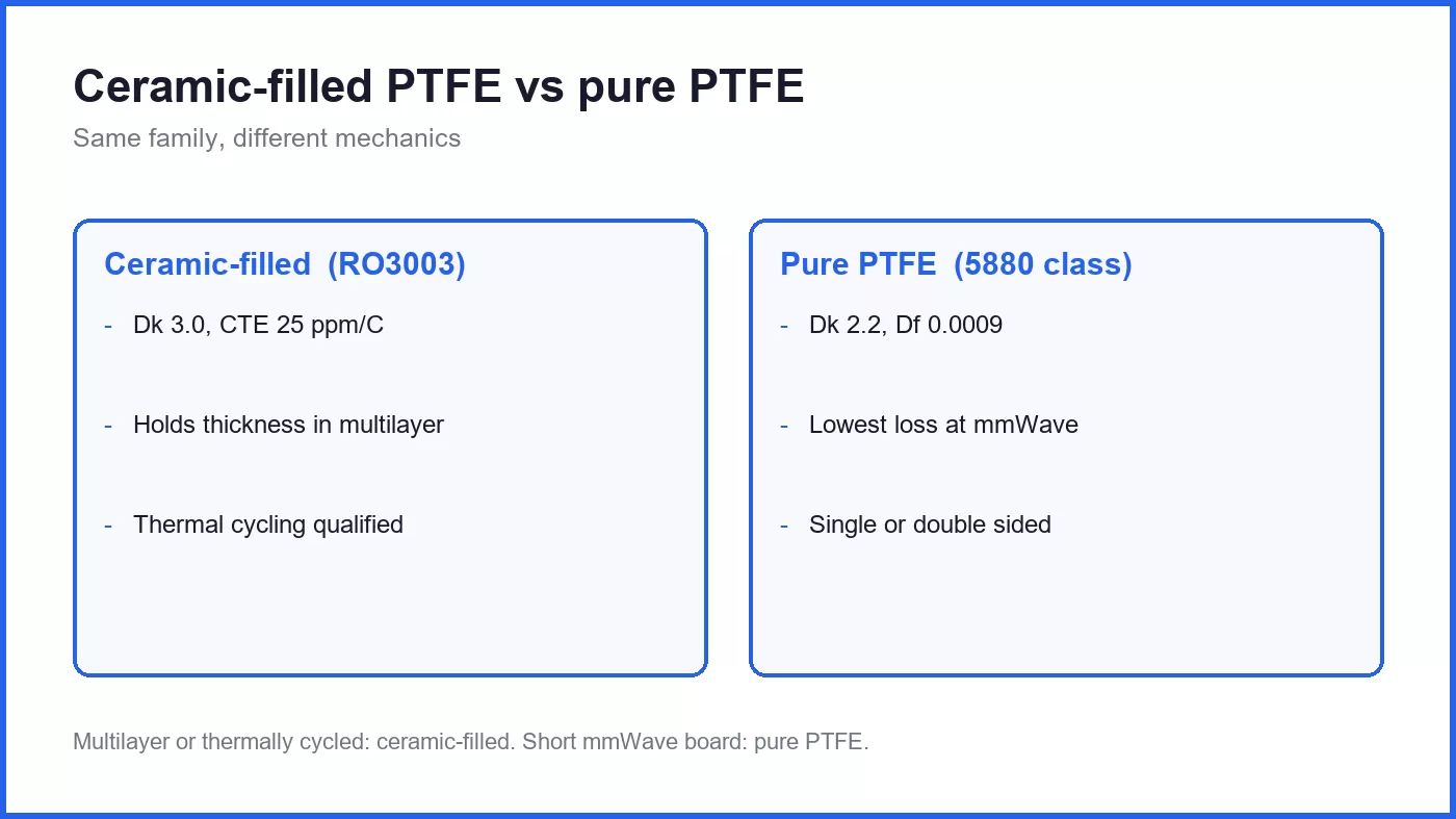
PTFE laminates are not one material. There are two families in common use, and they behave differently on the bench, in the press and in the price sheet. Ceramic-filled PTFE, such as RO3003 or RO3010, uses ceramic powder to raise Dk and to bring the coefficient of thermal expansion down towards copper. Pure or glass-reinforced PTFE, such as RT/duroid 5880, keeps Dk near 2.2 and Df near 0.0009 by staying close to virgin PTFE.
Choosing between them is not a matter of picking the lowest Df. The lower-Dk material makes every feature larger, the ceramic-filled material holds its dimensions better through thermal cycling, and the two drill and plate differently. This page lays out where each one belongs.
The families and their numbers
| Property | Ceramic-filled PTFE (RO3003 class) | Pure / glass-reinforced PTFE (5880 class) |
|---|---|---|
| Dk at 10 GHz | 3.00 (RO3003), up to 10.2 (RO3010) | 2.20 |
| Df at 10 GHz | 0.0010 | 0.0009 |
| CTE, Z axis | 25 ppm/°C | High, often 150–250 ppm/°C |
| Dimensional stability | Good, ceramic filler constrains movement | Poor, soft and prone to flow |
| Drill and route | Filled composite, cleaner cut | Gummy, smear-prone, needs sharp tools |
| Relative cost | High | Highest |
| Typical use | Antennas, filters, 24–77 GHz boards | Microwave and mmWave, low-Dk needs |
Why Dk 2.2 is sometimes the whole point
At 77 GHz, a microstrip line on Dk 2.2 is about 20 percent wider than the same impedance on Dk 3.0. Wider lines mean lower conductor loss for the same impedance, and at millimetre wave the conductor loss is the dominant term. This is why the lowest-loss microwave designs still use Dk 2.2 material even though the mechanical properties are worse.
The lower Dk also makes radiating elements larger, which helps antenna efficiency but hurts array pitch, exactly as it does when moving from RO4350B to RO3003. Above 60 GHz the trade is usually worth it; at 10 GHz it rarely is.
Where ceramic-filled PTFE wins
Anything that has to hold dimensions. Ceramic filler reduces Z-axis CTE from the 150 to 250 ppm/°C range down to around 25 ppm/°C. On a plated through hole, that is the difference between a barrel that survives thermal cycling and one that cracks after a few hundred cycles. For automotive radar or any board with a thermal cycling qualification, this alone decides the material.
Multilayer PTFE boards. Pure PTFE flows under pressure. A multilayer stack needs a material that keeps its thickness through lamination, otherwise the impedance of the inner layers moves. Ceramic-filled PTFE holds thickness far better, which is why most multilayer PTFE designs use it.
Boards that need a range of Dk values. The RO3000 family runs from Dk 3.0 to 10.2 in the same process family. A filter that needs a high-Dk layer for size reduction and a low-Dk layer for the feed can be built in one material system.
Drilling and routing. The filled material cuts more like a composite and less like soft plastic. Holes are cleaner, and the shop needs less special handling.
Where pure PTFE still wins
Millimetre wave front ends at 60 GHz and above. When the total loss budget is 3 dB and the board is 1 inch long, Df 0.0009 and Dk 2.2 versus Df 0.0010 and Dk 3.0 is a measurable difference in a link budget that has no margin.
Single or double-sided microwave boards. A stripline filter or a coupler on a 0.020" PTFE substrate does not need multilayer dimensional stability. The mechanical weakness does not matter because the board is one or two layers and mechanically supported by the housing.
Legacy designs. A large amount of defence and instrumentation hardware is qualified on 5880-class material. Re-qualifying on a ceramic-filled alternative costs more than the material difference, so the design stays where it is.
Processing differences that change the quote
Drilling. Pure PTFE requires sharp, often carbide, drills with a low feed rate, plus a desmear step that removes smear without destroying the dielectric. Ceramic-filled material is more forgiving but still needs a dedicated recipe; running either on an FR-4 program will produce smeared barrels that pass visual inspection and fail microsection.
Lamination. Pure PTFE needs a slow ramp and low pressure, otherwise the dielectric flows and the thickness drops. Ceramic-filled material tolerates a more normal cycle but still needs a PTFE-compatible prepreg or bondply. Neither can use standard FR-4 prepreg.
Surface preparation before plating. PTFE is chemically inert. Plasma treatment is standard for both families; the difference is in the time and gas mix, which the material supplier specifies and the shop has to follow.
Panel handling. Thin pure PTFE cores are floppy. They need support through the line, and a shop without that experience will produce handling damage that shows up as scrap, not as a process failure.
Cost reality
Both families are expensive relative to FR-4 and to hydrocarbon laminates. Pure PTFE is the most expensive of the common RF materials, and its yield in a shop that does not run it regularly is worse, which pushes the effective cost higher than the material price suggests.
Ceramic-filled PTFE sits below pure PTFE on material cost and usually above it on yield, so the gap in finished board price is larger than the laminate price difference. For a multilayer board with a thermal cycling requirement, the ceramic-filled option is almost always the cheaper total answer.
Decision rule
Start with frequency. Below 24 GHz, the loss difference between Dk 2.2 and Dk 3.0 materials is small on a short board, and the mechanical advantages of ceramic-filled PTFE decide it. Above 40 GHz, run the loss budget both ways: if the pure PTFE saves more than 0.5 dB on the critical path, it is worth the process cost.
Then check the mechanical requirement. Multilayer, thermal cycling, or a large panel: ceramic-filled. Single or double sided, mechanically supported, low loss budget: pure PTFE.
Finally, check who is building it. The best material in the wrong shop is a scrap lot. Ask for a microsection and a thermal cycle result on the first article, not just a first-article visual.
Related reading
- How Dk and Df Are Measured, and Why Datasheets Disagree
- Dk Drift: Why an RF Board Changes With Temperature and Humidity
- PTFE PCB Manufacturing: Process Control From Drill to Lamination
- RO4350B vs RO4003C: Which RF Laminate Should You Specify?
- RO3003 vs RO4350B for Antenna and Array Boards
- RF PCB manufacturing
- RF and microwave PCBA





