

A patch antenna is the one place where laminate choice shows up directly in radiated performance. Every 0.1 dB of feed loss is 0.1 dB off the gain, and every point of Dk error moves the resonant frequency. RO3003 and RO4350B sit at opposite ends of the price and performance scale for this job, and the decision usually comes down to frequency, array size, and how much the customer is willing to pay for the last half dB.
What each material is
RO3003 is a ceramic-filled PTFE laminate. Dk is 3.00 ±0.04 at 10 GHz and Df is 0.0010 at 10 GHz. It is soft, it drills and routes differently from FR-4, and it needs a PTFE-compatible prepreg or bondply in the stack.
RO4350B is a hydrocarbon and ceramic composite with no PTFE. Dk is 3.48 ±0.05 at 10 GHz and Df is 0.0037. It processes like FR-4, which is why most prototypes and most cost-driven antenna boards use it.
Side by side for antenna work
| Property | RO3003 | RO4350B | Effect on an antenna |
|---|---|---|---|
| Dk at 10 GHz | 3.00 | 3.48 | Patch size, feed impedance |
| Df at 10 GHz | 0.0010 | 0.0037 | Radiation efficiency, feed loss |
| Dk tolerance | ±0.04 | ±0.05 | Resonant frequency spread |
| CTE, Z axis | 25 ppm/°C | 32 ppm/°C | Plated hole reliability in thick panels |
| Moisture absorption | <0.02 % | <0.1 % | Frequency shift in humid environments |
| Process | PTFE: special drill, plasma desmear | FR-4-like | Cost per panel, yield |
The 8 percent patch that surprises people
Patch length is proportional to 1 over the square root of Dk. Moving from RO4350B at 3.48 to RO3003 at 3.00 makes every patch about 8 percent longer for the same resonant frequency. On a 10 GHz design that is roughly 0.5 mm on a 6 mm patch. It sounds trivial until the antenna is inside a housing with a fixed cavity, or the array pitch is fixed by the beam steering requirement.
Array pitch is the harder constraint. For grating-lobe-free scanning to ±60 degrees, element spacing has to stay below about half a wavelength in free space. A larger patch on the lower-Dk material can push the array pitch past that limit, and the fix is a different material or a different element, not a layout tweak.
Where the loss difference pays
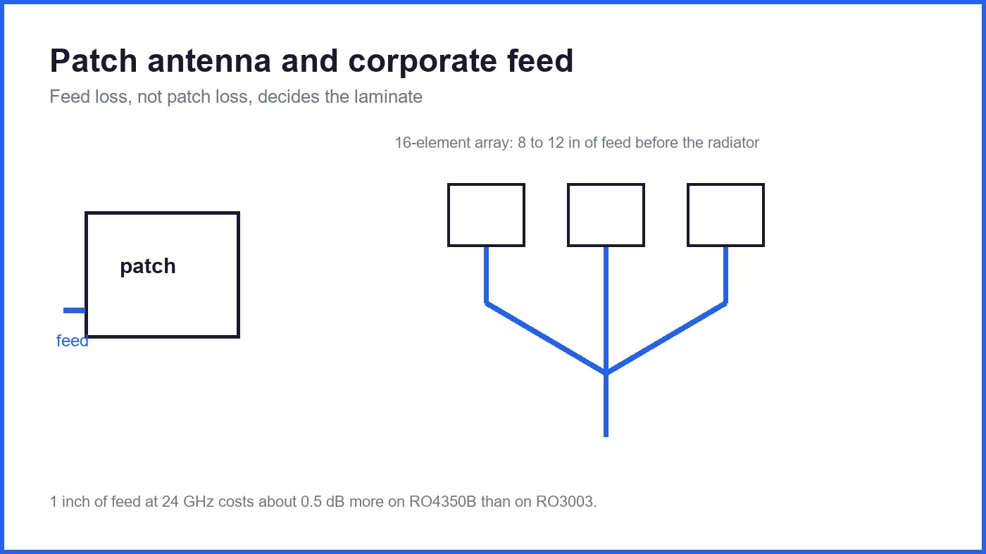
On a single patch with a short feed, the difference is small. On an array, the feed network dominates. A 16 element array with a corporate feed can carry 8 to 12 inches of trace from the input connector to the furthest element, plus the corporate splits.
At 10 GHz, RO4350B loses roughly 0.2 dB per inch more than RO3003 in the feed. Twelve inches means about 2.4 dB more loss, and in a passive array that is 2.4 dB off the gain before any active stage. At 24 GHz the gap is closer to 0.5 dB per inch, and at 77 GHz it is larger still.
That is the entire argument for RO3003 in radar and SATCOM arrays. It is not about the patch; it is about the feed.
Where RO4350B is the right answer
Sub-6 GHz antennas. Wi-Fi, LoRa, UHF RFID, 2.4 and 5.8 GHz modules: the feed is short, the loss difference is under 0.2 dB total, and the material cost difference is large.
Prototypes and low volume. A first antenna prototype on RO4350B can be built in a normal FR-4 shop with a normal drill recipe. The same design on RO3003 needs plasma desmear and a PTFE drill program, which adds days and cost to every iteration.
Boards that mix antenna and electronics. If the same board carries the transceiver, the power supply and the antenna, the FR-4-like processing of RO4350B is worth more than the RF loss difference, because the whole board has to survive reflow and conformal coating.
Where RO3003 is the only sensible choice
77 GHz automotive radar. At that frequency the loss difference per inch is around 1 dB, feed networks are long relative to wavelength, and the Dk tolerance directly shifts the resonant frequency of every patch in the array. Arrays here are specified on RO3003 or on similar PTFE materials, not on hydrocarbon laminates.
Large passive arrays with corporate feeds. Base station arrays, SATCOM user terminals, and phased array panels where the feed is longer than the radiator.
Humid or outdoor environments with tight frequency tolerance. The lower moisture absorption of PTFE keeps the resonant frequency stable through seasonal humidity, which matters for outdoor units that are tuned at the factory and never retuned.
The process side, which is where projects slip
Drilling. PTFE smears rather than cuts. RO3003 needs sharp drills, a reduced feed rate, and a desmear step that actually removes the smear without attacking the dielectric. A shop that runs it on an FR-4 recipe will pass the first article and fail on the third lot.
Lamination. PTFE does not flow like epoxy. The stack needs a compatible bondply, a slower ramp, and a press cycle from the material datasheet. Copper foil selection also matters: rolled annealed foil is common on PTFE for a reason, because it survives the thermal excursion without the same micro-crack risk as electrodeposited foil.
Panel size and support. Thin PTFE cores are flexible and need proper panel support through the line. A 0.005" RO3003 core on a large panel will sag in the conveyor if the shop has never run it.
Plated through holes. PTFE has a high CTE in the Z axis compared with FR-4 in absolute terms, and the soft dielectric gives less mechanical support to the barrel. Hole wall preparation and plating thickness matter more than on FR-4, and the acceptance criteria should be agreed before production, not after the first cross-section.
A practical decision rule
Calculate the feed loss budget first. Take the allowed loss from the antenna input to the furthest element, subtract the splitter losses, and divide by the trace length. If the number is above 0.4 dB per inch, RO3003 or an equivalent PTFE is the starting point. If it is below 0.2 dB per inch, RO4350B will pass and the money is better spent on the connector and the housing.
Then check three mechanical items: whether the patch size at the lower Dk still fits the array pitch, whether the shop can run PTFE with plasma desmear, and whether the board is a mixed RF and digital assembly. Any of those three can override the electrical answer.
Hybrid options
For arrays above 20 GHz it is common to use RO3003 only on the antenna layers and RO4350B or FR-4 on the feed and control layers below. The antenna sees the low-loss material, the digital section keeps FR-4 processing and cost, and the transition between the two is a controlled-impedance via or a coupled line.
The transition is where hybrid antenna boards fail. A via that looks fine on FR-4 can present a 1 to 2 dB discontinuity at 24 GHz if the pad and antipad geometry are not tuned for the layer stack. It should be simulated and measured on a coupon before the array is built, not discovered in the anechoic chamber.
Summary
RO3003 is the antenna material for millimetre wave and for large arrays with long feeds: Dk 3.00, Df 0.0010, stable over humidity, and processed like PTFE. RO4350B is the antenna material for sub-6 GHz, for prototypes, and for boards that mix antenna and electronics: Dk 3.48, Df 0.0037, processed like FR-4.
Decide on the feed loss per inch, then confirm patch size against array pitch and confirm the shop can run the material. The patch itself is rarely the reason to change laminate. The feed is.
Related reading
- MEGTRON6 vs MEGTRON7: When the Extra Loss Budget Is Worth It
- MEGTRON vs Rogers: Two Different Problems, Not Two Brands
- Ceramic-Filled PTFE vs Pure PTFE: Which RF Substrate?
- How Dk and Df Are Measured, and Why Datasheets Disagree
- Dk Drift: Why an RF Board Changes With Temperature and Humidity
- RF PCB manufacturing
- RF and microwave PCBA





