


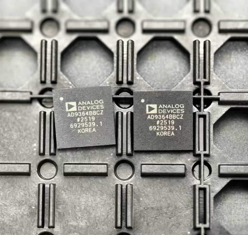

ADM213EARSZ
Brand: Analog Devices
Analog Devices ADM213EARSZ is a analog & mixed-signal component designed for Instrumentation and related applications. In stock at Superb Automation — request a quote for competitive pricing and fast delivery.
Product Specifications
ADM213EARSZ
Analog Devices — Analog & Mixed-Signal ICs
Product Overview
The ADM213EARSZ from Analog Devices is a high-performance analog / mixed-signal IC providing precision signal acquisition, conversion, and conditioning. Analog Devices (ADI) is a world leader in high-performance analog, mixed-signal, and DSP ICs for instrumentation, healthcare, automotive, and communications.
Superb Automation partners with leading brands including Qorvo, TI, ADI, XILINX, NVIDIA, Intel, ST, MACOM, Renesas, and Coilcraft to provide complete BOM and supply-chain solutions.
Key Features
- High-resolution data conversion with excellent SNR and THD
- Wide dynamic range and high linearity across operating conditions
- Integrated voltage reference with low temperature drift
- Flexible digital interface — SPI, I2C, or parallel options
- Industrial/automotive temperature range with guaranteed specs
- Low power consumption with power-down modes
Key Specifications
| Resolution | bits |
| Channels | — |
| Sample Rate | kSPS |
| Interface | — |
| Supply Voltage | V |
| Operating Temp | °C |
| Package | — |
| INL | LSB |
| SNR | dB |
| THD | dB |
Applications
Precision Instrumentation
Industrial Process Control
Medical Imaging & Diagnostics
Automotive Sensor Interfaces
Communications Infrastructure
Test & Measurement
Request Quote — In Stock, 100% New & Original, Full Warranty
ADM213EARSZ: five volt RS-232 interface with 15 kV pin protection
The ADM213EARSZ is a 5 V RS-232 line driver and receiver in a 28-lead SSOP, with four transmitters and five receivers, an enable input and the 0.1 uF charge pump of the E generation. It is bought where a serial port has to survive a cable plugged in by a user who is charged, and where the board has no room for the 1 uF capacitors the older parts needed.
Published values
| Parameter | Value |
|---|---|
| Interface | EIA-232E and CCITT V.28 |
| Drivers and receivers | 4 transmitters, 5 receivers |
| Data rate | 230 kbps guaranteed |
| ESD on RS-232 pins | 15 kV human body model, 8 kV contact, 15 kV air gap |
| Charge pump capacitors | 0.1 uF |
| Shutdown supply current | 10 uA typ, 25 uA max |
| Output swing | typically 9 V into the RS-232 load |
| Control | enable input on the ADM213E, shutdown on the ADM211E |
| Package and range | 28-lead SSOP, -40 C to +85 C |
The ESD rating and what it protects
The pin protection is quoted as 15 kV human body model, 8 kV contact discharge and 15 kV air gap discharge to IEC 1000-4-2. Those are three different tests and they protect against different events: the human body model describes a person touching a connector pin, the contact discharge describes a charged cable shell, and the air gap describes a spark before contact.
The protection is on the RS-232 pins only. The TTL side has ordinary logic levels and no such rating, so a fault on the logic side is a board level problem, not something this part absorbs. That distinction decides where the connector shield is bonded.
Why 0.1 uF capacitors change the board
The charge pump doubles and inverts the 5 V rail to produce the positive and negative transmitter levels, and the E generation does it with 0.1 uF capacitors instead of 1 uF. At 0.1 uF the parts are 0603 ceramics, which fit under the connector and do not need the electrolytic or tantalum footprint that older RS-232 circuits reserved.
The trade is ripple under load. The pump runs at a fixed frequency and the output droops between cycles by an amount set by the capacitor and the load current. At 230 kbps with a 3 kohm receiver load the droop is inside the specification; a lower data rate with a heavier cable capacitance is the case to check.
Four transmitters and five receivers
Nine signal lines in one package is what a full serial port plus a modem control set needs: two data lines, four handshake lines, and the ring indicator and carrier detect pair that many industrial ports still expect. The unused transmitters can be left unconnected, and each has an internal 400 kohm pull up on its input so an undriven TIN does not float.
The receivers have a 5 kohm pull down on the input, which holds an unconnected receiver output in the mark state rather than oscillating. That is the reason a port with no cable attached reads cleanly instead of producing framing errors.
Replacement and shortage notes
The ADM211E shares the pin out and the driver count but replaces the enable input with a full shutdown, so the two are not interchangeable on a board that toggles that pin. A candidate replacement has to match the charge pump capacitor value as well: a 0.1 uF part on a footprint laid out for 1 uF will work, the reverse will not.
The checks are pin count and control function, capacitor value, data rate, then the ESD rating on the pins that reach the connector. The pages below hold the cross references and the acceptance sequence.
Sourcing notes for this family: the pin to pin cross reference holds the cross references, how to verify a drop in replacement is the pre substitution check, and component lead time solutions is what we use when the part on the drawing is not on the shelf.
Two questions buyers ask
Is the ADM213EARSZ the same as the ADM211EARSZ? No. The ADM213E has an enable input, the ADM211E has a shutdown input that also disables the charge pump. The pin out is the same SSOP body but the control function is not.
What supply does it need? A single 5 V rail. The RS-232 levels are generated internally by the charge pump, so no negative supply is required.