


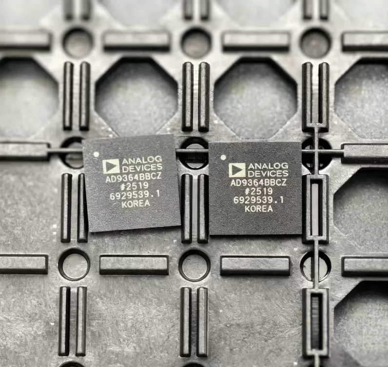

AD8624ARUZ
Brand: Analog Devices
Analog Devices AD8624ARUZ is a analog & mixed-signal component designed for Instrumentation and related applications. In stock at Superb Automation — request a quote for competitive pricing and fast delivery.
Product Specifications
AD8624ARUZ
Analog Devices — Analog & Mixed-Signal ICs
Product Overview
The AD8624ARUZ from Analog Devices is a high-performance analog / mixed-signal IC providing precision signal acquisition, conversion, and conditioning. Analog Devices (ADI) is a world leader in high-performance analog, mixed-signal, and DSP ICs for instrumentation, healthcare, automotive, and communications.
Superb Automation partners with leading brands including Qorvo, TI, ADI, XILINX, NVIDIA, Intel, ST, MACOM, Renesas, and Coilcraft to provide complete BOM and supply-chain solutions.
Key Features
- High-resolution data conversion with excellent SNR and THD
- Wide dynamic range and high linearity across operating conditions
- Integrated voltage reference with low temperature drift
- Flexible digital interface — SPI, I2C, or parallel options
- Industrial/automotive temperature range with guaranteed specs
- Low power consumption with power-down modes
Key Specifications
| Resolution | bits |
| Channels | — |
| Sample Rate | kSPS |
| Interface | — |
| Supply Voltage | V |
| Operating Temp | °C |
| Package | — |
| INL | LSB |
| SNR | dB |
| THD | dB |
Applications
Precision Instrumentation
Industrial Process Control
Medical Imaging & Diagnostics
Automotive Sensor Interfaces
Communications Infrastructure
Test & Measurement
Request Quote — In Stock, 100% New & Original, Full Warranty
AD8624ARUZ: quad precision amplifier in a 14-lead TSSOP
The AD8624ARUZ packs four of the AD8622 amplifiers into a 14-lead TSSOP body, at 215 uA typical per amplifier on a plus or minus 15 V supply and the same 125 uV maximum offset and 1.2 uV/C drift as the dual. It is the part for a four channel front end that has to fit one package without a fan of eight single amplifiers and their decoupling.
Published values
| Parameter | Value |
|---|---|
| Offset voltage, 25 C | 10 uV typical, 125 uV maximum |
| Offset voltage drift | 0.5 uV/C typical, 1.2 uV/C maximum, -40 to +125 C |
| Input bias current | 45 pA typical, 200 pA maximum at +-15 V |
| Supply current per amplifier | 215 uA typical, 250 uA maximum at +-15 V |
| Gain bandwidth | 560 kHz at +-15 V |
| Slew rate | 0.48 V/us at +-15 V |
| Voltage noise density | 11 nV/root Hz at 1 kHz, 0.2 uV p-p over 0.1 to 10 Hz |
| CMRR | 125 dB minimum at +-15 V |
| Input voltage range | -13.8 V to +13.8 V on a +-15 V supply |
| Output swing | 14.94 V minimum high into 100 k to ground |
| Short circuit current | 40 mA |
| Supply range | +-2.0 V to +-18 V |
| Package | 14-lead TSSOP, also offered in a 16-lead LFCSP |
Four channels in one body and the heat they make
Four amplifiers at 250 uA maximum is 1 mA, and on a plus or minus 15 V supply that is 30 mW in the package, which the 14-lead TSSOP handles without a thermal pad. The number that matters for a 4 mA loop transmitter is different: 1 mA of quiescent current is a quarter of the 4 mA at zero output, so the remaining 3 mA has to carry the sensor, the reference and the converter. Choose the AD8624 when the four channels share that budget, and two AD8622 packages when they do not.
The 16-lead LFCSP version has the exposed pad and a lower thermal resistance, which matters only if the board also puts a regulator or a reference in the same corner. For a signal board at 30 mW the TSSOP is the cheaper assembly and the easier part to rework.
Channel to channel behaviour
Four amplifiers on one die share a process and a temperature, so their offsets sit in a narrow band rather than at the two extremes of the 125 uV limit, and their drifts track. A four channel ratiometric measurement therefore keeps its channel to channel match better than four separate packages would, even though no matching specification is published. That is a process argument, not a data sheet line, so a circuit that needs a guaranteed match has to measure it or trim it.
Crosstalk between channels on one die is not specified either. At 560 kHz of gain bandwidth and 215 uA per channel the output impedance is high and the die is small, so a channel that drives a heavy load couples into its neighbours. Keep each output load above 10 k and the coupling stays below the offset of the channel it lands in.
What a quad saves on a bill of materials
One package instead of four, four decoupling capacitors instead of eight, and one placement instead of four are the visible savings. The invisible one is the amplifier count in the assembly drawing: a board with a single quad and a single reference is easier to inspect and to test than a board with a row of singles, and a substitution at the end of a build is a single line item.
The part is available in TSSOP and LFCSP with the same die, so a build that has to change package for a second source keeps the same offset and the same bandwidth and only the footprint moves. That is worth stating on the drawing so the second source does not arrive as a different amplifier.
When an order code in this family cannot be found, one stop BOM sourcing lists what else does the same job, the pin to pin cross reference covers what to check before a part is dropped into an existing board, and vendor consolidation is the route we take on a live shortage.
Two questions buyers ask
Is the AD8624ARUZ the same amplifier as the AD8622ARZ? Same core, different count and package: four channels at 215 uA each in a 14-lead TSSOP against two channels at 175 uA each in an 8-lead SOIC. The offset, drift and bandwidth lines are the same, so a channel moved from one to the other behaves the same and only the supply current and the footprint change.
Does it run from a single 5 V supply? The supply range is plus or minus 2.0 V to plus or minus 18 V, so 5 V single supply is inside it, but the input window is then 2.6 V wide and centred, which is the limiting factor rather than the supply.