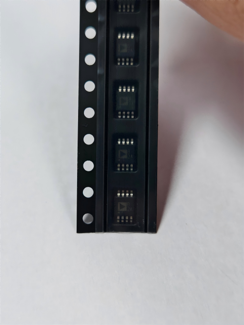

VBGQA1805
Brand: VBsemi
VBsemi VBGQA1805 is a discrete semiconductors component designed for AI Servers & Low-Altitude Economy (Drone and UAV) and related applications. In stock at Superb Automation — request a quote for competitive pricing and fast delivery.
Product Specifications
VBGQA1805
VBsemi — Discrete & Power Semiconductors
Product Overview
The VBGQA1805 from VBsemi is a discrete power semiconductor delivering efficient switching and power conversion. VBsemi (微碧半导体) specializes in discrete MOSFETs, power transistors, and protection devices for power supplies, motor control, and consumer electronics.
Superb Automation partners with leading brands including Qorvo, TI, ADI, XILINX, NVIDIA, Intel, ST, MACOM, Renesas, and Coilcraft to provide complete BOM and supply-chain solutions.
Key Features
- Low Rds(on) for minimal conduction losses in power switching
- Fast switching speed with low gate charge for high-frequency operation
- Avalanche-rated for robust operation under inductive load conditions
- High junction temperature rating for demanding environments
- Logic-level gate drive compatible for simplified design
- RoHS and AEC-Q101 qualified options available
Key Specifications
| Vds / Vce | V |
| Id / Ic | A |
| Rds(on) / Vce(sat) | mΩ |
| Qg | nC |
| Technology | — |
| Package | — |
| Configuration | — |
| Mounting | — |
Applications
Switch-Mode Power Supplies
Motor Drives & Inverters
Battery Management Systems
DC-DC Converters
Load Switching
Automotive Power Distribution
Request Quote — In Stock, 100% New & Original, Full Warranty
VBGQA1805: 80 V and 120 A at 4.5 milliohm
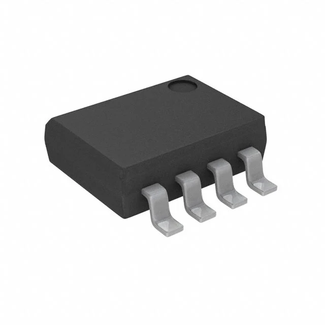
The VBGQA1805 is a single N channel MOSFET in a DFN8 body of 5 mm by 6 mm, rated at 80 V drain to source, plus or minus 20 V on the gate, a 3 V threshold, 120 A of drain current and 4.5 milliohm at a 10 V gate. It sits in the same family and the same footprint as the 2.65 milliohm member, at a higher resistance and a lower current.
That relationship is the reason this page is worth reading. Two parts in one footprint with the same voltage rating are a cost and loss decision, not a specification decision. The 2.65 milliohm part is larger silicon, so it is more expensive and it needs a better pad. The 4.5 milliohm part is cheaper and easier to build with, and at low current the difference in loss is small.
The 3 V threshold is slightly lower than the 3.5 V of the lower resistance member, which does not matter for a 10 V driver and does matter for a 5 V one. Both are inside the same family, so the same driver can usually serve both.
Key data for the VBGQA1805
| Configuration | Single N channel |
| Package | DFN8, 5 mm by 6 mm, exposed pad |
| VDS | 80 V |
| VGS | Plus or minus 20 V |
| Vth | 3 V typical |
| ID | 120 A, a die figure at a 25 C case |
| RDS(on) at 10 V | 4.5 milliohm |
| Technology | Shielded gate trench |
| Loss at 10 A | 0.45 W through the channel |
| Loss at 30 A | 4.05 W through the channel |
| Body diode | Intrinsic, cathode at the drain |
| Thermal path | Pad and vias, less demanding than the 2.65 milliohm part |
Choosing between 4.5 and 2.65 milliohm in one footprint
At 10 A the difference between the two parts is 0.19 W. At 20 A it is 0.74 W. At 40 A it is 3 W. So below about 20 A the cheaper part is the right choice on loss, and above 40 A the larger die earns its price. Between those two numbers the decision is about the copper and the ambient, not about the parts.
The larger die also has a larger gate charge, so at high frequency the smaller part can win even on total loss. A converter at 200 kHz with 20 A of average current may run cooler with the 4.5 milliohm part because the switching loss falls by more than the conduction loss rises.
Where the two parts differ most is in the safe operating area and the short circuit behaviour. A larger die absorbs more energy before the junction leaves its limit, so a hot swap or a fuse blowing event is easier on the lower resistance part. That is a reason to choose it even where the loss difference is small.
There is also a stocking argument. Two parts in one footprint let a line use the cheaper die for most builds and the larger die for the high current variants, without holding two sets of pads or two qualification paths. That is worth more than the few tenths of a watt difference at low current, and it is the usual reason a family like this is bought as a group rather than one code at a time. A buyer who holds both codes can cover a build that grows without a new part number or a new approval, which at the low current end is almost always cheaper than the extra silicon.
80 V on a 48 V rail, and the gate drive detail
The voltage margin is the same as for the other 80 V members: 64 V after derating, against a 58 V top of charge. A clamped transient fits, an unclamped load dump does not, and a regenerating load needs a brake.
At 4.5 milliohm and a 3 V threshold, a 5 V gate gets most of the way on. The resistance at 4.5 V is not printed on this page, so a 5 V driver has to be checked on the bench, but the gap from 3 V threshold to 4.5 V gate is a reasonable overdrive for a small die.
At 10 V the part is fully on and the switching edge is set by the gate resistor and the driver current. A 1 A driver with a 4.7 ohm resistor turns the die on in about 30 ns, which at 48 V is fast enough to need a tight power loop and a snubber across the switch.
Where the part fits and where it does not
It fits a 48 V load switch at 10 to 25 A, a synchronous rectifier on a 24 V output, a battery disconnect on a 36 V pack, a fan or pump driver on a 48 V rail, and a reverse polarity switch at moderate current. It does not fit a 48 A continuous path without a serious pad, a 96 V pack, or a hot swap position where the inrush energy is large.
For a footprint that can take either of two dies, the comparison is about loss at the working current and energy in a fault. Our how to reduce component cost page covers where a lower cost equivalent can be used and where the loss it adds outweighs the price difference.
The sourcing side of this part is covered on the strategic sourcing. For two dies that share one footprint, that page covers how the line is kept on a single approval across products.
Questions we get on this code
Is it a drop in for the 2.65 milliohm part? Same footprint, same voltage class, and a different die. The gate charge and the fault energy differ, so a hot swap position needs a check before the swap.
How much current at 25 C ambient? About 20 to 25 A with a pad on two ounce copper and a plane underneath, based on 2 to 3 W of loss. Above that the pad decides.
Can a 5 V rail drive it? Past the threshold, without reaching the printed 4.5 milliohm figure. Where the loss matters, use a 10 V driver.
What should a purchase order carry? Part number, DFN8 5 by 6, and the reel quantity. We confirm the packing on the offer.