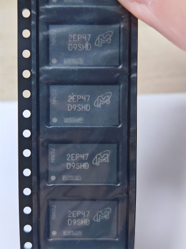
VBGQA1401S
Brand: VBsemi
VBsemi VBGQA1401S is a discrete semiconductors component designed for AI Servers & Low-Altitude Economy (Drone and UAV) and related applications. In stock at Superb Automation — request a quote for competitive pricing and fast delivery.
Product Specifications
VBGQA1401S
VBsemi — Discrete & Power Semiconductors
Product Overview
The VBGQA1401S from VBsemi is a discrete power semiconductor delivering efficient switching and power conversion. VBsemi (微碧半导体) specializes in discrete MOSFETs, power transistors, and protection devices for power supplies, motor control, and consumer electronics.
Superb Automation partners with leading brands including Qorvo, TI, ADI, XILINX, NVIDIA, Intel, ST, MACOM, Renesas, and Coilcraft to provide complete BOM and supply-chain solutions.
Key Features
- Low Rds(on) for minimal conduction losses in power switching
- Fast switching speed with low gate charge for high-frequency operation
- Avalanche-rated for robust operation under inductive load conditions
- High junction temperature rating for demanding environments
- Logic-level gate drive compatible for simplified design
- RoHS and AEC-Q101 qualified options available
Key Specifications
| Vds / Vce | V |
| Id / Ic | A |
| Rds(on) / Vce(sat) | mΩ |
| Qg | nC |
| Technology | — |
| Package | — |
| Configuration | — |
| Mounting | — |
Applications
Switch-Mode Power Supplies
Motor Drives & Inverters
Battery Management Systems
DC-DC Converters
Load Switching
Automotive Power Distribution
Request Quote — In Stock, 100% New & Original, Full Warranty
VBGQA1401S: 40 V and 1.1 milliohm in a 5 by 6 DFN
The VBGQA1401S is a single N channel MOSFET in a DFN8 body of 5 mm by 6 mm, rated at 40 V drain to source, plus or minus 20 V on the gate, a 3 V threshold, 200 A of drain current, 1.5 milliohm at a 4.5 V gate and 1.1 milliohm at 10 V. Both resistance columns are published, which is unusual and useful.
40 V is the class for a 12 V or 24 V rail with margin, for the synchronous rectifier of a 12 V output, for a hot swap switch on a 24 V backplane, and for the low side of a motor drive on a 24 V battery. The 200 A column is a die rating and it says more about the die area than about the current the body can pass.
Two resistance columns in one table let a circuit be compared at a logic level gate and at a rail level gate without guessing. The gap between 1.5 and 1.1 milliohm is 36 per cent, which tells you the die is close to fully enhanced at 4.5 V and gains only a little at 10 V.
Key data for the VBGQA1401S
| Configuration | Single N channel |
| Package | DFN8, 5 mm by 6 mm, exposed pad |
| VDS | 40 V |
| VGS | Plus or minus 20 V |
| Vth | 3 V typical |
| ID | 200 A, a die figure at a 25 C case |
| RDS(on) at 4.5 V | 1.5 milliohm |
| RDS(on) at 10 V | 1.1 milliohm |
| Technology | Shielded gate trench |
| Loss at 30 A, 4.5 V gate | 1.35 W through the channel |
| Body diode | Intrinsic, cathode at the drain |
| Thermal path | Pad and vias, no lead frame cooling worth counting |
Hot swap, inrush and the safe operating area
A part this low in resistance is often used as a hot swap switch, where it starts into a discharged capacitor bank and has to hold the current down while the bank charges. That mode is not about resistance at all. It is about the safe operating area: the die sits at the full bus voltage with the channel partly on, and the energy in the bank is dissipated inside a die whose thermal mass is small.
The 200 A column is not the number for that mode. What matters is the current the circuit limits during the ramp and the time it takes, and whether the die can absorb the energy without the junction leaving its limit. A 5 by 6 body has very little thermal mass, so a 24 V bank of 2000 microfarad charged in 5 ms is a serious event for the die, not for the package.
Where the current is controlled by a sense resistor and a controller, the die sees a defined current and the energy is bounded. Where the current is set only by the gate voltage, the die sees whatever the bank draws and the safe operating area curve is the only thing between the part and a short. A large die area helps here, and the curve remains the limit that decides the gate drive and the sense resistor.
Using 1.1 milliohm in a real current path
At 1.1 milliohm the switch is smaller than the board. A 5 mm length of two ounce copper 3 mm wide is about 0.4 milliohm, and a pair of connector contacts easily adds a milliohm. At 30 A the switch loses 1 W and the copper around it loses a similar amount, so the two have to be counted together when the loss budget is set, so a board that chooses the part on resistance alone leaves most of the loss in the wrong place.
Where the current is measured, the sense point decides the accuracy. A sense across the whole path measures the copper as well as the die, and the copper changes with temperature by 0.4 per cent per degree. A sense taken at the die, on the source pad, sees only the die and needs a Kelvin connection that most 5 by 6 footprints do not offer without care.
At 4.5 V gate the part is nearly at its best, which means a 5 V logic rail through a small resistor can drive it. That is a real advantage in a battery powered product where a 10 V driver rail is not available.
Where the part fits and where it does not
It fits a 12 V or 24 V load switch, a hot swap switch on a 24 V backplane with an active current limit, the synchronous rectifier of a 12 V output converter, a motor drive on a 24 V pack, and a reverse polarity switch where the body diode has to be bypassed. It does not fit a 48 V rail, a switch that has to hold off 40 V with a load dump, or a hot swap position where the inrush energy is not limited by a controller.
For a 40 V switch used as a hot swap element, the parameters that decide survival are the safe operating area, the gate clamp and the sense point. Our incoming inspection plan page covers what is measured when a reel arrives rather than after a board fails in the field.
The sourcing side of this part is covered on the PCBA test coverage strategy. For a hot swap switch on a 24 V board, that page covers what is tested on the line and what is left to the bench.
Questions we get on this code
Is 200 A usable? The die can take it at a 25 C case. The pad, the vias and the copper cannot on a normal board. Most products run this part at 20 to 60 A.
Can it be paralleled? Yes, and at 1.1 milliohm the copper between the sources is a large fraction of the total, so the copper arrangement of the two source paths decides the sharing.
What gate drive does it need? A 4.5 V rail through a small resistor gets to within 36 per cent of the best resistance. A 10 V rail is better where the driver allows it.
What should a purchase order carry? Part number, DFN8 5 by 6, and the reel quantity. We confirm the packing on the offer.