

HMC451LC3TR


Product Specifications
GaAs PHEMT MMIC medium power amplifier covering 5 to 20 GHz with 19 dB gain, +21 dBm saturated output and 21% PAE from a single +5 V supply.
Product Overview
The HMC451LC3TR is a GaAs PHEMT MMIC medium power amplifier that operates from 5 to 20 GHz and delivers 19 dB of gain with +21 dBm saturated output power at 21% power added efficiency. Input and output are 50 ohm matched and DC blocked, so the device needs no external matching components and can be dropped into a signal chain as a linear gain block.
The amplifier is used as a driver stage ahead of mixers, as a LO buffer, and as a general purpose gain block in microwave radios, VSAT terminals, test equipment and radar front ends. The 3 x 3 mm leadless QFN package is RoHS compliant and supports standard surface mount assembly.
The same die is offered in the LP3 package family. Selection between HMC451LC3TR and other package options comes down to board space, thermal path and assembly process rather than RF performance.
Key Features
- 19 dB gain – 16 dB minimum across 5 to 15 GHz, 14 dB minimum to 20 GHz
- +21 dBm saturated power – 21% PAE from a single +5 V supply at 114 mA
- +30 dBm output IP3 – linearity headroom for multi-carrier and complex modulation
- No external matching – 50 ohm matched I/O, DC blocked, no external components required
- 3 x 3 mm QFN – RoHS compliant leadless SMT package for standard reflow assembly
Key Specifications
| Parameter | Value |
|---|---|
| Frequency Range | 5 to 20 GHz |
| Gain | 19 dB typical (16 dB min, 5 to 15 GHz) |
| Gain Variation over Temperature | 0.015 dB/degC typical |
| Output Power at 1 dB Compression | +19.5 dBm typical |
| Saturated Output Power | +21 dBm |
| Output Third Order Intercept | +32 dBm (5 to 15 GHz) |
| Power Added Efficiency | 21% at saturation |
| Noise Figure | 7 dB typical |
| Input / Output Return Loss | 13 dB / 12 dB typical |
| Supply | +5 V at 114 mA |
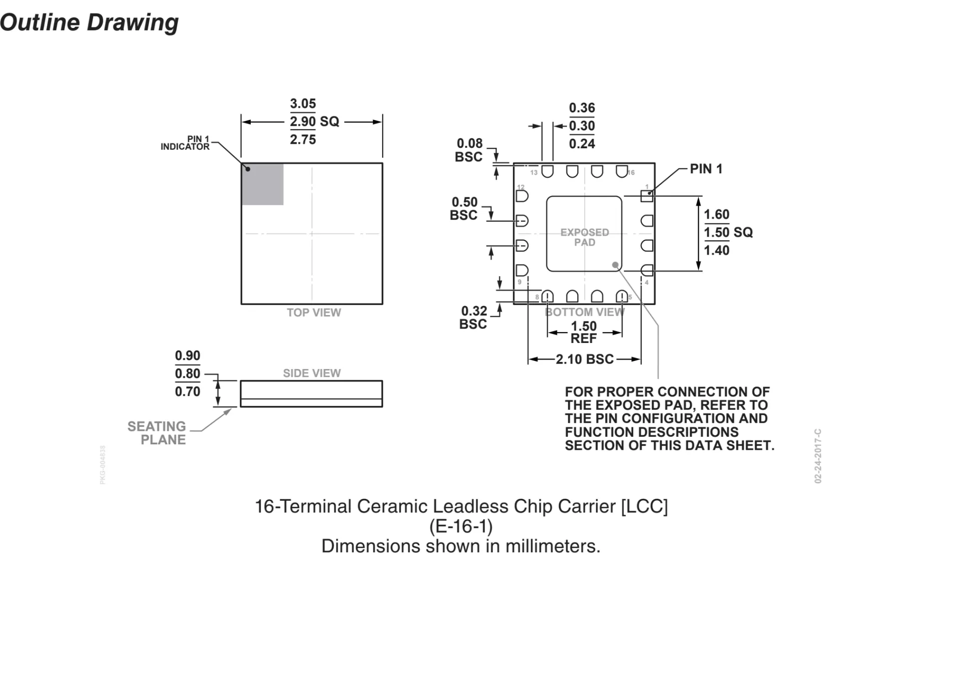
| Package | 3 x 3 mm QFN, 12 lead |
| Operating Temperature | -40 to +85 degC |
Applications
- Microwave radio and VSAT up-converter and down-converter chains
- Military and space payload front ends
- Test equipment and sensor RF paths
- Fiber optic analog transmitter drivers
- LO driver for HMC series SMT mixers
- Radar and EW receiver gain stages
HMC451LC3TR: One Part for 5 to 20 GHz, and Where It Runs Out of Gain
The HMC451LC3TR is a GaAs pHEMT medium power amplifier covering 5 GHz to 20 GHz in a 3 mm by 3 mm leadless package. It gives 19 dB of gain, +21 dBm saturated output at 21 percent efficiency from a single +5 V supply at 114 mA, +30 dBm output intercept, a noise figure of 6.5 to 7 dB, 50 ohm matched and DC blocked ports, and a 3 x 3 mm surface mount body.
Three band segments, three gain numbers
The electrical table splits the band and the gain with it: 19 dB typical and 16 dB minimum from 5 to 15 GHz, 18 dB typical and 15 dB minimum from 15 to 18 GHz, 17 dB typical and 14 dB minimum from 18 to 20 GHz. A link budget that carries 19 dB across the whole band is 2 dB optimistic at 20 GHz and 5 dB optimistic against the minimum at the top segment. The part still covers 5 to 20 GHz, which is two octaves from one reel, but the flatness claim belongs to the typical column.
Drive level at compression
At 0.57 W of DC and 21 percent efficiency the amplifier adds 119.7 mW of RF, so reaching +21 dBm, or 125.9 mW, needs 6.2 mW of input, which is 7.9 dBm. The gain at that point is 13.1 dB, roughly 6 dB below the small signal figure. The part is therefore easy to drive and hard to overdrive, and a preceding stage that can deliver 10 dBm will push it into compression on purpose.
Choosing against the HMC441LC3B
The two packaged amplifiers overlap heavily in band and differ in the numbers that matter. The HMC451LC3 has more gain, 19 dB against 14 dB, reaches 15 dBm lower at the bottom of the band, and covers 5 to 20 GHz against 6 to 18 GHz. The HMC441LC3B has a slightly higher saturated output, +21.5 dBm against +21 dBm, a better noise figure in its lower band and 24 mA less supply current. Two HMC441LC3B in cascade give 28 dB of gain with a 4.6 dB noise figure by the usual cascade relation, which is more gain and less current than two HMC451LC3 at 38 dB and 0.57 W each.
Published figures
| Parameter | Value |
|---|---|
| Band | 5 GHz to 20 GHz, two octaves |
| Gain by segment | 19 dB at 5 to 15 GHz, 18 dB at 15 to 18 GHz, 17 dB at 18 to 20 GHz |
| Gain minimum | 16 dB, 15 dB and 14 dB in the same segments |
| Saturated output | +21 dBm at 21 percent efficiency |
| Supply and current | +5 V at 114 mA, 0.57 W |
| Drive at saturation | 7.9 dBm, gain falls to 13.1 dB |
| Output intercept | +30 dBm, 10.5 dB above P1dB |
| Noise figure | 6.5 to 7 dB |
| Die version | 22 dB, +22 dBm, 24 percent, 1.27 mm by 1.27 mm |
| Package | 3 mm by 3 mm leadless, DC blocked ports |
Selection notes
- The DC blocked ports remove the need for series capacitors, which matters where the amplifier sits between two bias tees.
- Supply bypassing follows the datasheet list of 100 pF, 1000 pF and 2.2 uF per drain pin, and both drain pins are fed separately.
- At 7 dB of noise figure the part is a driver, a local oscillator buffer or a general gain block, never a front end.
- Two octaves in one package reduces the number of part numbers a multiband radio has to carry, which is a logistics saving as much as a technical one.
- The die version is 3 dB stronger in gain and 1 dB stronger in output, so a module that can take die should compare before accepting the packaged limits.
Buyer questions
Will it hold 19 dB at 20 GHz? The typical column says 17 dB and the minimum says 14 dB in the 18 to 20 GHz segment. A budget that needs 19 dB at 20 GHz needs a second stage or a different part.
Is the HMC441LC3B a drop in replacement? No. Both are 3 mm by 3 mm leadless amplifiers in the same family but the pin functions and the bias arrangement differ, and the gain differs by 5 dB.
Category page: Analog and mixed-signal ICs. For the driver, switch and attenuator parts around it see RF component sourcing, and for amplifier equivalents see amplifier cross reference.
Why Choose Superb Automation
- RF and microwave IC sourcing from franchise and authorized supply channels, with lot traceability on every shipment
- Cross-reference and alternative part support when the original device is on allocation or end of life
- BOM review before quotation, so package, temperature grade and screening level match the design intent
- Sample and prototype quantities alongside production volumes, from the same supply path
- Incoming inspection and X-ray verification available for critical RF lots
- One year warranty on new and original parts, with technical support from engineers who work on RF boards daily