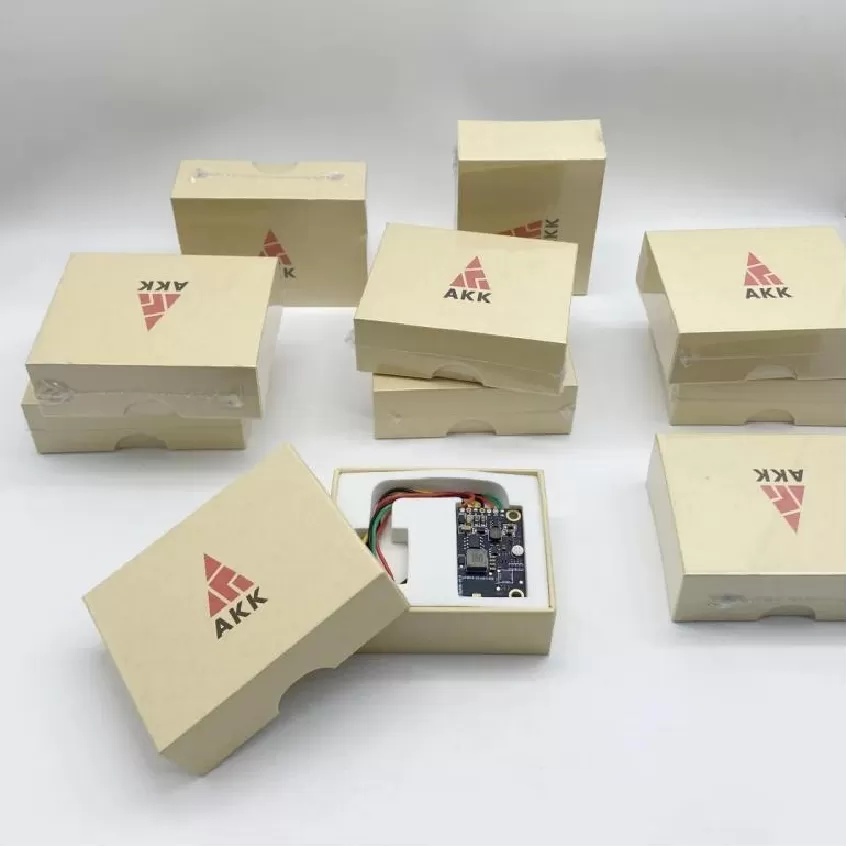
Telemetry Communication Board (RF) PCBA
Telemetry Communication Board RF PCBA. UAV Avionics PCBA, Flight Control Board, FPV Transmitter, Navigation Fusion, Mission Control, Video Transmission, DO
Product Specifications
Telemetry Communication Board (RF) PCBA
Purpose-Built UAV Telemetry Downlink — -148 dBm Sensitivity, Adaptive Rate — DO-160 / IPC-6012 Class 3
Product Overview
The Telemetry Communication Board (RF) from Superb Automation is a purpose-built PCBA optimized exclusively for the reliable downlink of UAV telemetry data — flight parameters, GPS coordinates, battery status, system health diagnostics, and environmental sensor readings — from the aircraft to the ground control station. Unlike general-purpose communication boards that must balance voice, video, and data, this board dedicates its entire channel capacity to telemetry, achieving link budgets and reliability levels that multi-purpose radios cannot match. The board implements a proprietary adaptive data rate protocol that dynamically adjusts spreading factor, coding rate, and bandwidth in response to real-time signal-to-noise ratio measurements, maintaining connectivity even as the UAV transitions between line-of-sight and obstructed environments. All fabrication meets IPC-6012 Class 3 standards.
The PCBA is built on a 4-layer RF-grade substrate with a dedicated continuous ground plane optimized for the 433 MHz and 868/915 MHz ISM bands. The RF front-end employs a two-stage LNA with SAW filter pre-selection, achieving receiver sensitivity of -148 dBm at the lowest data rate. A TCXO provides ±1 ppm frequency stability across the full temperature range, eliminating the frequency drift that plagues crystal-based oscillators in thermally challenging UAV environments and meeting DO-160 temperature/altitude requirements. The digital section uses an STM32L4 ultra-low-power microcontroller that buffers telemetry data during link interruptions and replays it upon reconnection, ensuring no data loss during momentary signal dropouts caused by airframe shadowing. AES-128 encryption is applied on-the-fly to all telemetry data.
Key Specifications
| Frequency Bands | 433 / 868 / 915 MHz |
| Receiver Sensitivity | -148 dBm @ SF12 |
| Tx Power | +27 dBm |
| Frequency Stability | TCXO ±1 ppm |
| Data Buffer | 2 MB onboard flash |
| MCU | STM32L4, ultra-low-power |
| Protocol | MAVLink 2.0, adaptive data rate |
| Encryption | AES-128 on-the-fly |
| Standards | DO-160, IPC-6012 Class 3 |
| Link Budget | >165 dB @ 433 MHz |
Adaptive Data Rate Protocol
The proprietary adaptive rate engine continuously monitors SNR and RSSI, adjusting LoRa spreading factor (SF7–SF12), coding rate (4/5–4/8), and bandwidth (7.8–500 kHz) to maximize throughput while maintaining a target packet error rate below 1%. During BVLOS transitions where the airframe temporarily shadows the antenna, the data buffer stores up to 2 MB of telemetry for replay upon link restoration. The TCXO-based timing reference ensures that frequency error remains under 200 Hz across the full temperature range, critical for narrowband LoRa modes where frequency offset can degrade sensitivity by several dB.
Test Strategy
Receiver sensitivity is measured at all data rate configurations using a calibrated RF signal generator with BER measurement. Transmitter power output is calibrated across all bands to ±0.5 dB. Frequency stability is verified from -40 °C to +85 °C against a GPS-disciplined reference. The data buffer function is tested by simulating link interruptions of varying duration and verifying complete data recovery upon reconnection. Each board ships with a calibrated test report.
More information