



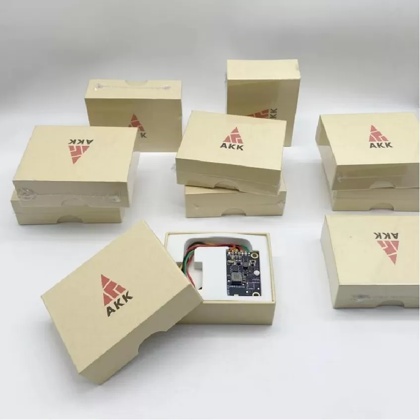
Wireless Communication Board PCBA
Wireless Communication Board PCBA. UAV Avionics PCBA, Flight Control Board, FPV Transmitter, Navigation Fusion, Mission Control, Video Transmission, DO-254
Product Specifications
Wireless Communication Board PCBA
Multi-Protocol Mesh Radio — Wi-Fi 6, BT 5.2 AoA, LoRa, Zigbee/Thread with Radio Resource Manager
Product Overview
The Wireless Communication Board is a multi-protocol short-range communication PCBA designed to enable UAV swarm coordination, inter-drone mesh networking, and seamless integration with ground-based IoT infrastructure. While long-range telemetry radios handle the UAV-to-ground link, there is a growing need for direct drone-to-drone communication in swarm operations, drone-to-infrastructure links for smart city and industrial IoT integration, and ad hoc networking for collaborative missions. This board addresses all these use cases by integrating Wi-Fi 6 (802.11ax), Bluetooth 5.2, LoRa (868/915 MHz), Zigbee 3.0, and Thread mesh networking onto a single compact PCBA.
The 4-layer PCB features three independent radio transceivers with careful antenna placement and isolation to allow simultaneous multi-protocol operation. The Wi-Fi/Bluetooth combo is handled by an NXP 88W8987 chipset supporting dual-band (2.4/5 GHz) Wi-Fi 6 with OFDMA and MU-MIMO, plus Bluetooth 5.2 with direction-finding capability using angle-of-arrival (AoA) antenna arrays. The sub-GHz radio is a Semtech SX1262 providing LoRa and FSK modes for long-range mesh links between drones up to 10 km apart. A dedicated Silicon Labs EFR32MG24 SoC handles Zigbee 3.0 and Thread protocol stacks with hardware-accelerated AES-128 encryption for secure mesh networking. An onboard Ethernet-to-Wi-Fi bridge enables transparent wireless extension of the UAV's wired avionics network. All three radios are controlled through a central STM32H7 application processor that implements a radio resource manager, dynamically allocating time, frequency, and power across the three radios to avoid self-interference.
Key Specifications
| Wi-Fi | 802.11ax (Wi-Fi 6), dual-band 2.4/5 GHz |
| Bluetooth | 5.2 with AoA direction finding |
| LoRa | 868/915 MHz, mesh capable |
| Mesh Protocols | Zigbee 3.0 + Thread |
| Security | AES-128 hardware-accelerated |
| Network Bridge | Ethernet-to-Wi-Fi transparent |
| Application Processor | STM32H7, radio resource manager |
| Antennas | 3× U.FL, optimized isolation |
PCBA Assembly Challenges
Assembling a multi-radio board with three simultaneously operating transceivers requires careful management of RF isolation at the assembly level. The three U.FL antenna connectors must be placed with maximum physical separation, and each connector's ground plane must be contiguously stitched to the inner ground plane to avoid creating unintentional radiating slots. The NXP 88W8987 Wi-Fi/BT chipset is a QFN package with a large exposed thermal pad; achieving >75% solder coverage on this pad is critical for both thermal performance and RF grounding. The Semtech SX1262 LoRa transceiver operates in the sub-GHz band where board-level parasitics are less critical, but its TCXO reference oscillator must be placed within 5 mm of the IC with a guarded trace to minimize frequency pulling. Antenna matching networks — series and shunt LC components — are placed on each RF path and tuned during production testing if required. The three radio sections are separated by ground plane splits with ferrite-bead bridges for DC power, ensuring that digital noise from the STM32H7 does not couple into the sensitive LNA inputs.
Test Strategy
Each assembled Wireless Communication Board undergoes comprehensive multi-radio testing. All three radios are validated individually for transmit power, receive sensitivity, and frequency accuracy using a Rohde & Schwarz CMW500 wideband radio communication tester. Wi-Fi 6 throughput is tested under OFDMA multi-user scenarios; Bluetooth 5.2 is validated for AoA direction-finding accuracy using a calibrated antenna array reference. LoRa range is verified using conducted sensitivity measurements at the lowest data rate (SF12, 125 kHz BW) with a target sensitivity of -137 dBm. Radio coexistence testing runs all three radios simultaneously — Wi-Fi streaming at maximum throughput, Bluetooth in a continuous ACL connection, and LoRa transmitting at maximum duty cycle — while measuring packet error rate on each radio; the resource manager must maintain PER below 1% on all links. Mesh network formation is validated with a minimum of 4 units forming a Zigbee and Thread network. The Ethernet-to-Wi-Fi bridge is tested for transparent forwarding at line rate.
PCB Manufacturing Difficulty
The 4-layer PCB uses a controlled-impedance stack-up with tight dielectric tolerances (±10%) to maintain consistent RF impedance across the Wi-Fi 2.4/5 GHz bands. The top layer is dedicated to RF traces (50 Ω microstrip and coplanar waveguide), while layer 2 is an unbroken RF ground plane. Layers 3 (power) and 4 (digital) carry the DC and digital signals, isolated from the RF plane by the core dielectric. The Wi-Fi 5 GHz traces have a width of approximately 0.35 mm for 50 Ω on the selected laminate, with an etch tolerance of ±20 µm. The U.FL connector footprints require precision drilling for the center pin pad (0.7 mm diameter) with tight positional tolerance (±0.05 mm) to ensure consistent impedance transition from the PCB trace to the connector. The board uses standard FR-4 (Tg 150°C) which is adequate for sub-6 GHz operation. All boards undergo TDR testing on impedance coupons for 50 Ω verification. The three antenna connector regions are visually inspected for proper ground stitching via placement and density.
More information