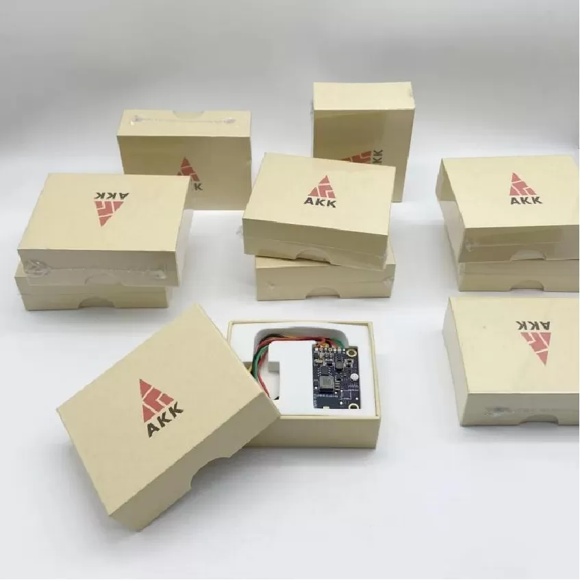
FPV Receiver Module Board PCBA
FPV Receiver Module Board PCBA. UAV Avionics PCBA, Flight Control Board, FPV Transmitter, Navigation Fusion, Mission Control, Video Transmission, DO-254, D
Product Specifications
FPV Receiver Module Board PCBA
Dual Diversity FPV Receiver — <5 µs Antenna Switching, <1.0 dB NF — DO-160 / IPC-6012 Class 3
Product Overview
The FPV Receiver Module Board from Superb Automation is a dual-antenna diversity receiver PCBA that delivers maximum video link reliability for FPV ground stations and goggles. In FPV flying, the received video signal is subject to multipath interference as the drone maneuvers around obstacles — at any given moment, one antenna may be in a deep signal null while the other receives a strong signal. This board continuously monitors the received signal strength indicator (RSSI) on both antenna inputs and instantaneously selects the better signal, switching in under 5 microseconds to avoid any visible glitch in the video stream. An alternative combining mode sums both signals with phase correction for enhanced sensitivity in weak-signal conditions. The board is fabricated to IPC-6012 Class 3 and meets DO-160 RF susceptibility requirements.
The 4-layer PCB employs two independent RF front-ends, each with its own LNA, SAW filter bank, and downconversion mixer, feeding a shared baseband demodulator. The LNAs are based on the Skyworks SKY65943 with a noise figure below 1.0 dB and gain of 16 dB, providing the sensitivity needed to pull weak signals from distant drones. The board covers all 40 standard FPV channels across the 5.650–5.950 GHz band, with channel selection via an SPI interface controlled by the host system. An onboard video amplifier conditions the demodulated composite video signal to drive either a direct display input or a video digitizer for recording. The board also outputs RSSI as an analog voltage for real-time signal strength display in the pilot's OSD (on-screen display).
Key Specifications
| Antenna Configuration | Dual diversity, SMA |
| Antenna Switch Time | < 5 µs |
| LNA Noise Figure | < 1.0 dB |
| Receiver Sensitivity | -98 dBm @ 6 MHz BW |
| Channels | 40 channels, 5.650–5.950 GHz |
| Video Output | Composite 1 Vpp, 75 Ω |
| RSSI Output | 0–3.3 V analog |
| Host Interface | SPI + analog video |
| Standards | DO-160, IPC-6012 Class 3 |
| LNA Device | Skyworks SKY65943 |
Diversity Architecture
The dual-diversity architecture employs continuous RSSI monitoring on both channels with a comparator-based decision circuit that switches antennas in under 5 µs — faster than a single video line period, ensuring no visible artifacts in the displayed image. The switching decision is hysteretic, preventing oscillation when both antennas receive nearly equal signal levels. In combining mode, the two RF paths are phase-aligned through a variable delay line and summed coherently, providing up to 3 dB of effective sensitivity improvement in weak-signal conditions. Each RF path includes an independent SAW filter with 20 MHz bandwidth centered on the selected channel, providing >35 dB of adjacent channel rejection.
Test Strategy
Diversity switching performance is verified using two calibrated RF signal generators with independent amplitude modulation to simulate multipath fading. The switching threshold, speed, and glitch-free video output are validated with a high-speed oscilloscope. Receiver sensitivity is measured at all 40 channels with BER < 1×10⁻³ at -98 dBm. RSSI linearity is calibrated across the full dynamic range (-98 to -20 dBm). Each board is tested with commercial FPV transmitters to verify real-world interoperability.
More information