

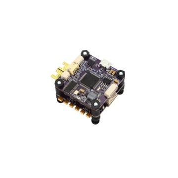

A drone BOM is a weight and power budget with a supply chain attached. Every gram saved in the flight controller or the speed controller is paid back in flight time, and every watt of loss becomes heat in a sealed frame with no airflow. The parts that decide the flight are rarely the expensive ones, and the hardest to replace are often the small ones.
Where drone UAV component choices go wrong
Single sourced inertial sensing is the first risk. An IMU is calibrated part by part, and a replacement with a different bias stability changes the attitude estimate at the same time as it changes the calibration procedure. The BOM that lists one part number with no alternative and no lifecycle check carries the whole flight control risk in one line.
Speed controller derating is the second. The MOSFETs in an ESC are chosen for the current at the propeller, and the current at the propeller is not the current in the datasheet test. Gate charge, switching loss at the commutation frequency and the thermal path through the board decide whether the stage survives a punch out at low battery, and a part with lower on resistance can still run hotter if its gate charge is higher.
RF link margin is the third. The transmitter, the front end filter and the receiver chain are bought as three parts and behave as one link. A filter with more insertion loss than the reference, or a power amplifier with lower gain at the band edge, removes margin that the range test was relying on, and the effect appears as a shorter link rather than a failed part.
Vibration is the fourth. Connectors, crystals and the packages of the inertial parts are all sensitive to the airframe and the motors, and a part that passes a bench test can produce intermittent contacts on a frame that resonates. The board stiffness belongs to the component choice, because the package and the mounting decide the stress.
Lifecycle closes the list. Flight controller silicon and IMUs are retired on the maker schedule, not the airframe schedule, and an airframe that is meant to be supported for eight years needs a second source identified before the first one disappears.
The components that decide a drone UAV build
| Component group | What decides the choice | What a weak comparison looks like |
|---|---|---|
| Inertial sensor | Bias stability, range and vibration coupling decide the attitude estimate | Axes and interface matched, drift not compared |
| Flight controller MCU | Core, peripherals and timing decide the loop rate and headroom | Pin count matched, loop headroom not measured |
| ESC MOSFETs | Gate charge, on resistance and thermal path decide survival at current | On resistance compared, switching loss ignored |
| RF front end | Gain and loss at the band edges decide the link margin | Centre frequency compared, edges not measured |
| GNSS module | Constellation, update rate and lifecycle decide navigation support | Position accuracy quoted, update rate and support not checked |
| Power management | Rails, sequencing and efficiency decide heat and start behaviour | Output current compared, sequencing not compared |
| Fuel gauge | Ageing model and current sense decide the remaining flight time | Voltage based estimate accepted as a gauge |
| Connectors | Retention under vibration and mating cycles decide reliability | Pin count and pitch matched, retention not compared |
| Passives and crystals | Temperature drift and mechanical robustness decide stability | Value and tolerance compared, drift not compared |
| Memory and logging | Write endurance and temperature range decide data integrity | Capacity compared, endurance and grade ignored |
How SUPERB PCBA supports a drone UAV component choice
Send the BOM with the frame mass budget, the rail voltages, the loop rate the flight controller has to hold, the vibration environment, the link range and the build quantity. The reply compares candidates against the table above and marks every difference as compatible, needs a check, or needs a board change, with the measurement that would settle each open point.
The board families are grouped under UAV avionics PCBA, and the flight control silicon side is collected on the flight controller MCUs for UAV and drone control boards page. Where the inertial sensor is the risk, the parameter comparison is set out in the IMU selection guide, and where a part is short on the open market the routes are collected under component lead time solutions.
Provenance comes before the sample. Reels are counted by X-ray, markings and date codes are inspected, and decapsulation is used where the risk justifies it, because flight controller silicon and inertial parts are both common targets for re marking. Verified lots carry a 730 day warranty, and a substitution only enters the BOM after written approval from your side.
Proving the components on the airframe, not on the bench
A UAV board is qualified after assembly. Reflow stress, board stiffness and the mass of the parts change the vibration response, and the thermal path through the copper decides whether the ESC stage survives a hover at high ambient. The measurement that matters is taken on the assembled board at the temperature and vibration the airframe produces, and SUPERB Tech keeps that record against the build so the next batch is compared with the first one rather than with an opinion.
SUPERB Assembly builds and tests those boards: first article inspection against released data, 3D SPI before reflow, 3D AOI after it, X-ray in 2D and CT mode with voiding below 5 percent, and functional test on a fixture approved by your team that logs loop timing, sensor output and link behaviour. The work runs under IPC-A-610 Class 2 and Class 3 and ISO 9001, with boards supported from 500 MHz to 77 GHz, impedance held to plus or minus 5 percent, up to 68 layers, and conformal coating where the airframe sees humidity.
Drone UAV component questions
Can a pin compatible IMU replace the qualified part?
It can fit, and it will still need calibration, a vibration check and a flight test, because the bias stability and the axis behaviour are part specific. The pin map is the smallest part of the question.
Is a MOSFET with lower on resistance always cooler?
No. Switching loss depends on gate charge and commutation frequency, and a part with lower conduction loss can run hotter if it switches more slowly in the same gate drive.
How is a second source proved on a flight controller?
With the loop timing measured on the assembled board, the peripherals exercised at the real rates, and a flight test against the existing tune. A bench link test does not show the timing margin.
What if the replacement changes the package height?
Then the mass distribution and the clearance change with it, and the change is quoted with the mechanical check and the test plan so the effect on the airframe is known before the order.
Next step
Send the BOM with the mass budget, the rails, the loop rate, the vibration environment, the link range and the annual quantity. You get the comparison with each difference marked, the candidate list with availability and lifecycle status, and the measurements needed to release a change.





