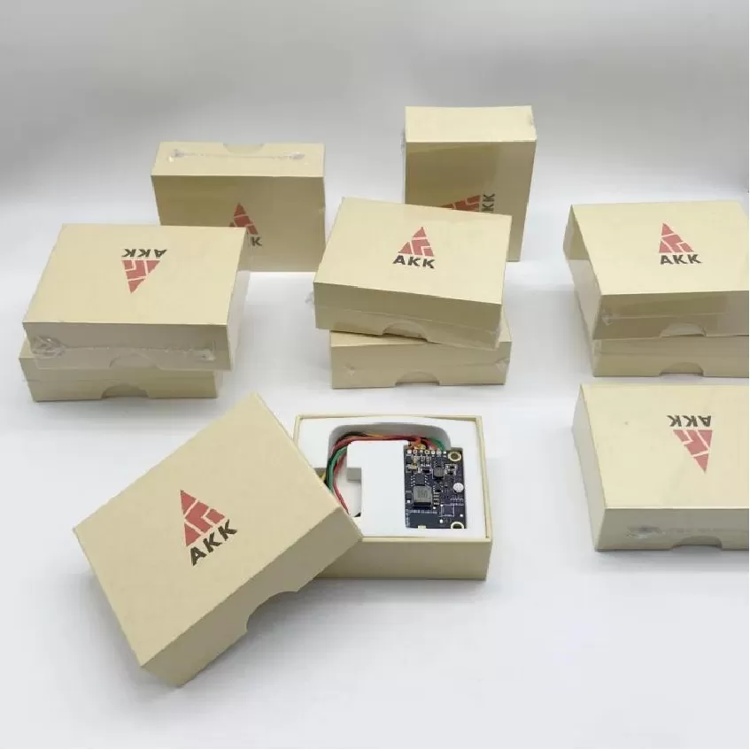
Signal Relay Board PCBA
Signal Relay Board PCBA. UAV Avionics PCBA, Flight Control Board, FPV Transmitter, Navigation Fusion, Mission Control, Video Transmission, DO-254, DO-160,
Product Specifications
Signal Relay Board PCBA
Full-Duplex Store-and-Forward RF Relay — 80 dB Isolation, GPS-TDMA — DO-160 / IPC-6012 Class 3
Product Overview
The Signal Relay Board from Superb Automation is a specialized PCBA designed to extend UAV communication range through store-and-forward signal regeneration. Operating as an airborne or ground-based relay node, this board receives, amplifies, digitally regenerates, and retransmits communication signals between a UAV and its control station when direct line-of-sight is obstructed by terrain, buildings, or the Earth's curvature during long-range BVLOS missions. The board functions at the physical layer — it does not decode or interpret the communication protocol, making it transparent and compatible with any modulation scheme operating within its frequency band, including LoRa, FSK, GFSK, and OFDM waveforms. All fabrication meets IPC-6012 Class 3 requirements for high-reliability RF boards.
The 4-layer PCB incorporates two complete RF chains — one for the uplink direction and one for the downlink — each with independent PAs, LNAs, and SAW filters. A high-isolation RF circulator and band-pass filtering achieve >80 dB of isolation between the transmit and receive paths, allowing full-duplex operation on a single antenna without the need for bulky and lossy duplexers. The digital regeneration section samples the received signal at 4× oversampling, performs clock and data recovery (CDR) using a digital PLL, and regenerates a clean, jitter-free version of the original signal for retransmission. This eliminates the noise accumulation that plagues analog repeaters and allows cascading of up to 8 relay nodes. An onboard GPS receiver provides precise timing for TDMA slot synchronization in multi-node relay networks. The board is qualified to DO-160 environmental standards.
Key Specifications
| Operational Mode | Full-duplex, single antenna |
| TX/RX Isolation | >80 dB |
| Signal Regeneration | CDR + jitter cleanup, 4× oversampling |
| Frequency Bands | 433 / 868 / 915 / 2400 MHz |
| Relay Latency | < 200 µs |
| Synchronization | GPS-disciplined TDMA |
| Max Cascade Depth | Up to 8 nodes |
| Power Consumption | 5 V, 1.5 W typical |
| Standards | DO-160, IPC-6012 Class 3 |
| Transparency | Protocol-agnostic, any modulation |
Relay Network Architecture
The GPS-disciplined TDMA scheme enables up to 8 relay nodes to operate on the same frequency without collision. Each node occupies a fixed time slot of 2 ms in a repeating 16 ms frame, with guard intervals to accommodate propagation delay between nodes. The onboard GPS receiver provides both 1PPS timing reference and position data for adaptive slot assignment based on node topology. The CDR and regeneration stage eliminates accumulated jitter, allowing signals to traverse multiple relay hops without degradation in bit error rate. The 80 dB TX/RX isolation enables simultaneous reception and transmission on a single antenna, halving the antenna count compared to conventional dual-antenna relay designs.
Test Strategy
Every assembled board is characterized for relay gain, group delay, and adjacent channel rejection across all frequency bands. TX/RX isolation is verified with a vector network analyzer. CDR jitter transfer and jitter tolerance are measured using a BERT (bit error rate tester) with injected sinusoidal jitter. GPS-TDMA synchronization is tested with a multi-node simulator. Cascade performance is validated by connecting up to 8 boards in series and measuring end-to-end BER with no measurable degradation compared to a direct link.
More information