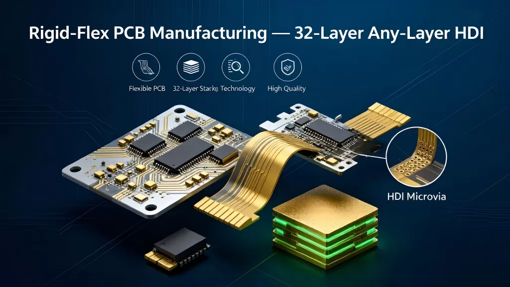
Rigid-flex PCBs combine rigid FR-4 sections with flexible polyimide layers in a single integrated assembly — eliminating connectors and cables between boards, reducing assembly weight, and removing failure points. Superb Automation manufactures rigid-flex boards up to 32 layers with 5+N+5 any-layer HDI structures, 0.03/0.03 mm fine-line capability on both inner and outer layers, and layer-to-layer registration within ±0.02 mm. The process supports aerospace flight hardware, medical implantables and wearables, automotive camera modules, and military-grade electronics where space and reliability are critical.
Rigid-Flex Manufacturing Parameters
Max Layer Count
32 layers, 5+N+5 any-layer HDI
HDI Structure
5+N+5 any-layer, copper-filled stacked micro-vias
Max Board Thickness
4.0 mm
Min Board Thickness (4L)
0.3 mm
Min Flex PCB Width
1.5 mm
Max Finished Board Size
700 × 480 mm
Min Line/Space — Inner
0.03 / 0.03 mm
Min Line/Space — Outer
0.03 / 0.03 mm
Layer-to-Layer Registration
±0.02 mm
Hole-to-Conductor Position
±0.10 mm
Max Finished Copper
3 oz
Through-Hole Min
≥ 0.15 mm
Blind Via Min
0.05 mm
Through Via Aspect Ratio
20:1
Blind Via Aspect Ratio
1:1
Hole Position Tolerance — Through
±0.025 mm
Hole Position Tolerance — Blind
±0.025 mm
PTH Tolerance
±0.075 mm
NPTH Tolerance
±0.05 mm
Press-Fit Hole Tolerance
±0.05 mm
Slot Hole Tolerance
±0.10 mm
Outline Tolerance
±0.10 mm
Controlled Impedance
50Ω single-ended; 85Ω / 100Ω differential; ±5% standard (±2% critical)
Surface Finishes (Rigid Sections)
ENIG, ENEPIG, hard gold, immersion tin / silver, OSP
Rigid-Flex Build-Up Structures
Build-Up
Description
Typical Via Structure
1+N+1
One build-up layer per side of the core. Entry-level density, lowest cost.
Blind micro-vias L1→L2 and L(N)→L(N-1)
2+N+2
Two build-up layers per side, stacked micro-vias. Mainstream for compact modules.
Stacked vias L1→L2→L3
3+N+3
Three build-up layers per side. High routing density for space-critical designs.
Stacked through all build-up layers
5+N+5 (Any-Layer)
Five build-up layers per side — every layer connects to every other layer. Maximum density for the most compact rigid-flex designs.
Copper-filled stacked micro-vias through all layers; sequential lamination
Rigid-Flex Materials & Construction
Rigid Sections
Base Material
High-Tg FR-4 (standard), halogen-free available
Copper
Electro-deposited copper, up to 3 oz
Solder Mask
LPI green (standard); other colors available
Flex Sections
Base Material
Polyimide film (DuPont Kapton or equivalent) — thin, flexible, high-temperature rated for solder reflow
Copper
Rolled annealed copper — higher flexibility and fatigue resistance vs. electro-deposited
Coverlay
Polyimide coverlay with acrylic or epoxy adhesive — protects flex traces while maintaining flexibility
HDI Structure — 5+N+5 Any-Layer
The 5+N+5 any-layer HDI structure places five build-up layers on each side of an N-layer rigid-flex core. Stacked copper-filled micro-vias enable any layer to connect to any other layer — delivering maximum routing density for the most compact rigid-flex designs. Sequential lamination and precision laser drilling maintain ±0.02 mm registration through all build-up cycles.