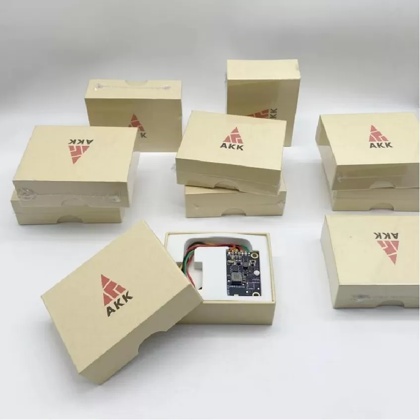
Flight Stability Control Board PCBA
Flight Stability Control Board PCBA. UAV Avionics PCBA, Flight Control Board, FPV Transmitter, Navigation Fusion, Mission Control, Video Transmission, DO-2
Product Specifications
Flight Stability Control Board PCBA
Dedicated 8 kHz Stabilization Augmentation with Triple-Redundant IMU — DO-254 / IPC-6012 Class 3
Product Overview
The Flight Stability Control Board is a dedicated stabilization augmentation PCBA engineered by Superb Automation to deliver exceptional flight smoothness and gust rejection for UAV platforms operating in turbulent conditions. Unlike a general-purpose flight controller, this board is specifically optimized for real-time gyro-stabilized corrections, employing a dedicated triple-redundant IMU array with sensor fusion running at 8 kHz — eight times faster than conventional flight controllers. The board's primary function is to detect and counteract high-frequency disturbances such as wind gusts, propeller imbalances, and mechanical vibrations before they propagate into the flight path. All hardware and firmware development follows DO-254 Design Assurance processes.
The PCBA is built on a 6-layer low-noise PCB with isolated analog and digital ground planes connected at a single star-point to minimize ground-loop interference. The analog front-end for the gyroscope and accelerometer signals features precision low-noise operational amplifiers with anti-aliasing filters tuned to the sensor bandwidth. A dedicated Cortex-M4 processor handles the high-speed inner-loop control at 2 kHz, independently of the main flight controller, providing attitude-rate damping and angular acceleration limiting. Communication with the primary flight controller occurs over a dedicated CAN-FD bus running at 5 Mbps, ensuring deterministic low-latency data transfer compliant with DO-160 conducted emissions requirements.
Key Specifications
| IMU Array | Triple-redundant, 8 kHz sample rate |
| Processor | Cortex-M4, 200 MHz |
| Control Loop Rate | 2 kHz inner stabilization loop |
| Bus Interface | CAN-FD, 5 Mbps |
| PCB | 6-layer, split analog/digital planes |
| Gyro Range | ±2000 dps |
| Accelerometer Range | ±16 g |
| Latency | < 125 µs sensor-to-output |
| Standards | DO-254, DO-160, IPC-6012 Class 3 |
| Noise Floor | < 0.005 dps/√Hz gyro noise density |
Sensor Fusion Architecture
The triple-redundant IMU array employs a voting and mid-value-select fusion strategy that detects and excludes a faulty sensor within one control cycle. Each IMU is placed on a separate axis of mechanical isolation to prevent common-mode vibration coupling. The analog front-end achieves a noise density below 0.005 dps/√Hz for the gyroscope channels, enabling detection of angular accelerations as low as 0.1 dps². The star-point grounding scheme achieves >60 dB of digital-to-analog isolation, preventing processor switching noise from contaminating the sensor signal chain.
Test Strategy
Every assembled board undergoes vibration-table characterization across a 5–2,000 Hz swept-sine profile, measuring noise density, bias stability, and cross-axis sensitivity. The three IMUs are verified to agree within 0.1 dps across the full rate range. CAN-FD communication is tested with injected bus errors and validated for frame loss rate under worst-case bus loading. The complete sensor-to-output latency is measured using a high-speed optical reference to verify the 125 µs specification.
More information