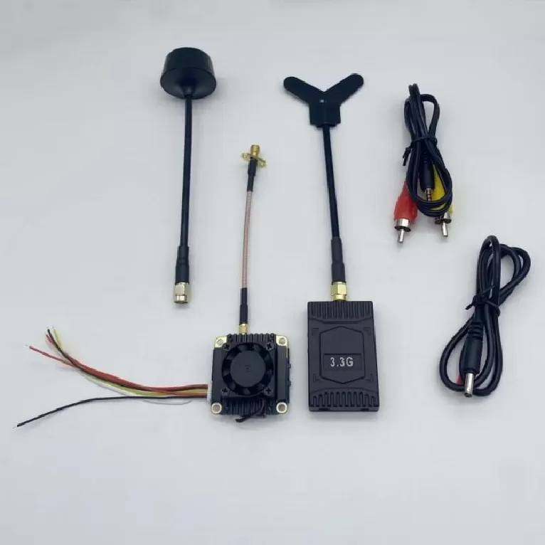
RF Mixer Board PCBA
RF Mixer Board PCBA. RF PCBA, Power Amplifier, LNA, RF Front-End, Phased Array, Beamforming, Antenna Array, Frequency Synthesizer, Rogers PCB, VNA Test, Mi
Product Specifications
RF Mixer Board PCBA
High-Linearity Frequency Conversion for Wideband Receivers, Downconverters, and Spectrum Analyzers
Product Overview
The RF Mixer Board PCBA provides high-linearity frequency conversion from 2 to 18 GHz using both passive diode-ring and active FET mixer topologies optimized for specific frequency plans and dynamic range requirements. Our passive mixer designs achieve IIP3 figures exceeding +25 dBm with only 6.5 dB of conversion loss, making them ideal for receiver front-ends where intermodulation performance directly determines the system's spur-free dynamic range. The board layout incorporates LO/RF isolation structures — grounded guard rings, via fences, and coplanar waveguide shielding — that achieve better than 40 dB of port-to-port isolation without external filtering, suppressing LO leakage that can desensitize upstream LNAs and create LO-radiated EMI. For active mixer configurations where conversion gain is required, integrated LO buffer amplifiers reduce the external LO drive requirement to 0 dBm while maintaining the phase noise performance of the system reference. Each mixer board includes onboard IF filtering — typically a lumped-element or distributed lowpass or bandpass filter — to suppress the LO feedthrough and unwanted image products, simplifying the downstream IF chain. Full characterization includes conversion loss/gain versus frequency, port-to-port isolation, input IP3, input P1dB, and a comprehensive spurious output table across the entire specified frequency range. Essential building block for frequency converters, spectrum analyzers, electronic warfare receivers, and wideband downconverters.
Key Specifications
| RF/LO Frequency Range | 2–18 GHz |
| IF Frequency Range | DC – 4 GHz |
| Conversion Loss (passive) | 6.5 dB typical |
| Input IP3 | +25 dBm |
| LO-to-RF Isolation | >40 dB |
| LO Drive Level | +13 dBm (passive) / 0 dBm (active) |
| PCB Material | Rogers 5880 / RO3003 |
| Layer Count | 4–6 layers, LO/RF isolation planes |
PCBA Assembly Challenges
Mixer board assembly at 18 GHz demands precision placement of the mixer core elements. For passive diode-ring mixers, the four Schottky diode quads must be placed with mirror symmetry around the balun center — a 50 µm radial offset in one diode unbalances the ring and degrades port-to-port isolation by 5–10 dB. The LO and RF baluns (typically planar Marchand or transformer types) require precise solder fillet control on the coupled-line sections; excess solder on one side of a balanced structure creates an amplitude imbalance that reduces image rejection. For active FET mixers in QFN packages, the exposed pad underneath the IC serves as both the RF ground and the primary thermal path — void-free soldering verified by X-ray is mandatory to prevent thermal runaway at elevated LO drive. The IF output trace carries DC through the bias-tee and must be routed with adequate current-carrying capacity for active mixer drain current. All bond wires in open-cavity hybrid mixer designs are inspected under 20× magnification for loop height uniformity.
Test Strategy
Mixer characterization begins with conversion loss/gain measurement: a calibrated signal generator drives the RF port while a spectrum analyzer measures the IF output; the LO is supplied by a second synthesized source. This measurement is swept across all RF/LO frequency combinations in the specified range to generate the full conversion loss matrix. Port-to-port isolation is measured with a VNA: LO-to-RF (S31), LO-to-IF (S32), and RF-to-IF (S21) in both upconverter and downconverter configurations. IIP3 is measured with a two-tone RF input (tones separated by 1 MHz) while measuring the third-order intermodulation products at the IF output. The spurious table is generated by stepping the RF and LO across a grid of frequencies and recording every spur above -80 dBc at the IF port — typically a 100×100 point grid. A subset of boards undergoes temperature characterization from -40°C to +85°C to verify conversion loss stability.
PCB Manufacturing Difficulty
Mixer PCB fabrication at 18 GHz requires ultra-low-loss laminate (Rogers 5880 with Df = 0.0009 or RO3003 with Df = 0.0010) to minimize insertion loss in the passive structures. The balun designs — whether Marchand, rat-race, or transformer-coupled — rely on precise coupled-line geometries where the even-mode and odd-mode impedances are set by conductor width and spacing. Spacing variation of ±0.5 mil shifts the balun center frequency by 200–500 MHz at 18 GHz. The LO and RF input traces must be isolated by a continuous ground plane with no breaks for the entire length from connector to mixer core — any gap creates a coupled-line structure that transfers LO power to the RF port. Microstrip-to-stripline transitions at the mixer core input require backdrilled vias with stub lengths under 5 mil to avoid stub resonance within the 2–18 GHz band. Finished boards are verified on a VNA with full 4-port calibration across 10 MHz to 20 GHz.
More information