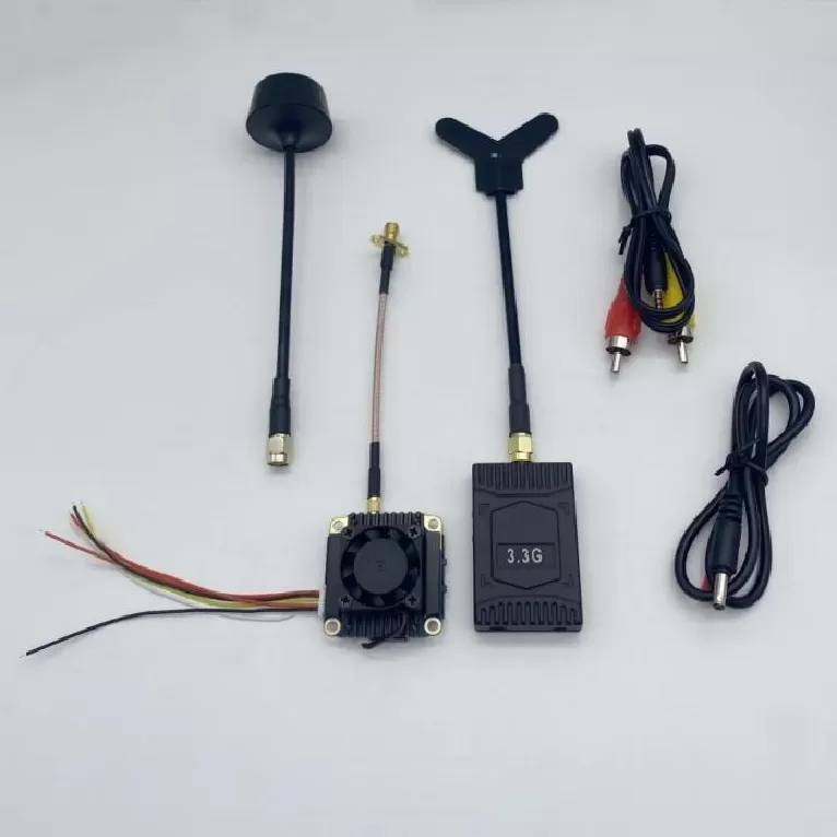
HF System Board PCBA
Hf System Board PCBA. RF PCBA, Power Amplifier, LNA, RF Front-End, Phased Array, Beamforming, Antenna Array, Frequency Synthesizer, Rogers PCB, VNA Test, M
Product Specifications
HF System Board PCBA
Fully Integrated HF Transceiver on a Single Board — Tx, Rx, Synthesizer & T/R Switching, 1.5–30 MHz, 100 W PEP
Product Overview
The HF System Board PCBA integrates a complete HF transceiver signal chain — transmitter, receiver, frequency synthesizer, and T/R switching — onto a single multi-layer PCB assembly. The receiver path features a triple-conversion architecture with software-defined IF processing, achieving better than 0.25 μV sensitivity (10 dB SINAD) with exceptional strong-signal handling from the high-level first mixer. The transmitter chain delivers 100 W PEP output with better than -45 dBc harmonic suppression through integrated low-pass filter banks. An onboard DDS-driven PLL synthesizer provides 1 Hz tuning resolution with low phase noise, supporting both voice (SSB, AM, FM) and digital mode operation. System-level isolation design uses compartmentalized shielding, independent voltage regulation per section, and strategic placement of RF absorbing material to achieve stability with all sections simultaneously active. The digital interface includes an onboard audio codec, CAT control via USB, and direct IQ access for external SDR processing. Every board undergoes a full transceiver performance test including sensitivity, selectivity, transmit power, and spurious emissions. This PCBA is a complete HF radio on a single board, ready for integration into manpack radios, vehicular communication systems, and fixed-station HF transceivers.
Key Specifications
| PCB Type | HF System Board |
| Frequency Range | 1.5–30 MHz |
| Architecture | Integrated Tx / Rx / Synthesizer |
| Tx Power | 100 W PEP |
| Material | Rogers 4003C / Megtron 6 |
| Layer Count | 10–14 layers, system integration |
PCBA Assembly Challenges
Assembling a fully integrated HF transceiver on a single board is one of the most complex PCBA challenges in the RF industry. The board simultaneously hosts a high-power transmitter chain (100 W PEP), an ultra-sensitive receiver front-end (0.25 μV), a low-noise frequency synthesizer, and high-speed digital control circuitry — all within inches of each other. The assembly sequence is carefully staged: SMT components are placed and reflowed in two passes. The first pass places all digital and low-power analog components using a standard SAC305 profile. The second pass places the high-power transmitter components — including the power amplifier transistors, output transformer, and low-pass filter banks — using a higher-temperature profile with nitrogen atmosphere to ensure complete wetting of the large thermal-mass components. The PA transistors (typically LDMOS or GaN in bolt-down flange packages) are mounted to a copper heat spreader that is pre-attached to the PCB using thermal interface material before the transistors are soldered. Inter-stage shielding walls are installed after SMT assembly using conductive gasket material that maintains RF isolation while allowing serviceability. The T/R switching PIN diode network requires symmetric layout and matched component placement to maintain isolation symmetry between transmit and receive paths. Every transmitter assembly undergoes a progressive power-on sequence: bias verification at low voltage, then gradual power ramp while monitoring current, temperature, and output spectrum to catch assembly defects before they cause catastrophic failure at full power.
Test Strategy
The HF System Board undergoes the most comprehensive test sequence of any Superb Automation PCBA, essentially a full transceiver acceptance test performed on every unit. The receiver path is tested first: sensitivity is measured at 10 frequencies across 1.5–30 MHz using a calibrated signal generator, verifying that 10 dB SINAD is achieved at 0.25 μV or better. Selectivity is tested by measuring the receiver's response to signals at ±5 kHz and ±20 kHz offsets, confirming the IF filter shape factor. The synthesizer phase noise is measured at 10 kHz offset using a phase noise analyzer, and the tuning resolution is verified by stepping the synthesizer in 1 Hz increments and confirming lock at each step. The transmitter is tested into a calibrated 50-ohm dummy load: output power is measured across all bands, harmonic content is verified below -45 dBc using a spectrum analyzer, and carrier suppression (for SSB) is measured. The T/R switching time is measured by toggling the PTT line and capturing the RF envelope at the antenna port — switching must be complete within 5 ms. Spurious emissions are measured from 100 kHz to 1 GHz in both transmit and receive modes, confirming compliance with FCC Part 97 and MIL-STD-461 limits. The digital interface is exercised by sending CAT commands via USB and verifying response. Finally, a 2-hour burn-in test operates the transceiver in a repeated 5-minute transmit / 5-minute receive cycle at full power to identify any infant mortality failures before shipment.
PCB Manufacturing Difficulty
Fabricating the bare PCB for an HF system board requires the most demanding mixed-technology stackup in the HF product line. The 10–14 layer board must simultaneously support high-current transmitter traces (carrying up to 5 A of PA drain current), sensitive low-level receiver traces (carrying sub-microvolt signals), and high-speed digital buses. The Rogers 4003C RF layers provide low-loss performance for the receiver front-end and synthesizer, while the Megtron 6 digital layers support the high-speed processor and memory interfaces. The hybrid stackup requires careful material selection for the bonding layers to match CTE between the dissimilar laminates and prevent delamination during reflow. The high-current transmitter traces use 3 oz/ft² copper with wide geometries on dedicated inner layers, thermally isolated from the sensitive receiver layers by continuous ground planes with no splits or voids. The synthesizer VCO section uses a dedicated ground pour with minimal via connections to the main ground plane to prevent digital noise injection. All receiver input traces are surrounded by ground guard traces with via stitching to prevent stray coupling. Finished boards undergo 100% automated optical inspection, flying probe continuity testing of all nets, and high-pot testing of the PA drain traces to ground to verify dielectric integrity under the high-voltage transmitter operation. A sample from each lot is cross-sectioned to verify inter-layer registration and plating quality.
More information