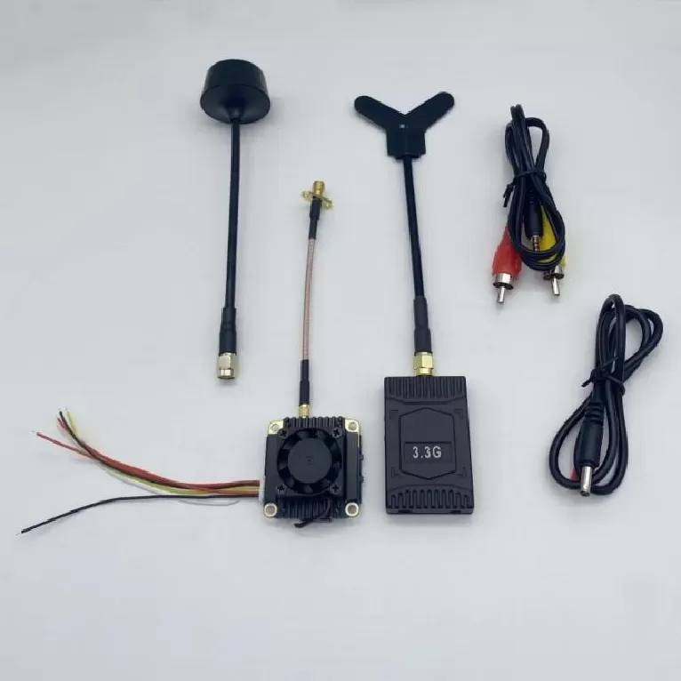
RF Signal Chain Board PCBA
RF Signal Chain Board PCBA. RF PCBA, Power Amplifier, LNA, RF Front-End, Phased Array, Beamforming, Antenna Array, Frequency Synthesizer, Rogers PCB, VNA T
Product Specifications
RF Signal Chain Board PCBA
End-to-End Antenna-to-Baseband Receiver Chain — 6–10 Layer Controlled-Impedance PCB with Cascaded Gain Staging
Product Overview
The RF signal chain board PCBA delivers a fully integrated, simulation-verified receiver path from the antenna input connector through to the baseband ADC interface. Each gain stage, filter, and attenuator is systematically placed and isolated to satisfy the cascaded noise figure, linearity, and dynamic range budgets of mission-critical receivers. The chain incorporates a front-end LNA stage optimized for sub-3 dB noise figure, one or more intermediate gain blocks, digitally controlled step attenuators (DSA) with 0.5 dB resolution, and band-select filter banks that provide 40+ dB out-of-band rejection. Impedance-controlled 50-ohm microstrip and stripline routing maintains better than 15 dB return loss at every inter-stage port. The entire chain from 10 MHz to 6 GHz is pre-simulated using cascaded S-parameter models, with simulated gain flatness held to ±1 dB across each sub-band. This solution is engineered for spectrum monitoring receivers, direction-finding arrays, and wideband SIGINT platforms where channel-to-channel amplitude and phase consistency directly determine system-level accuracy.
Key Specifications
| Layer Count | 6–10 layers |
| Material | Rogers 4350B / FR-4 hybrid |
| Surface Finish | ENIG per IPC-4552 |
| Min. Trace/Space | 6/6 mil (RF), 4/4 mil (digital control) |
| Impedance Control | 50 Ω single-ended ±10% |
| Frequency Range | 10 MHz – 6 GHz |
| Cascaded Gain | 40–80 dB (configurable in 0.5 dB steps) |
| Cascaded Noise Figure | < 3.0 dB (at maximum gain) |
PCBA Assembly Challenges
Assembling a multi-stage RF signal chain requires careful management of isolation between gain stages to prevent feedback paths that cause oscillation or gain ripple. Each gain block is placed in its own shielded compartment — either through physical shielding fences soldered to the PCB or through grounded via-wall isolation — achieving better than 60 dB of reverse isolation between adjacent stages. The LNA input stage uses specialized low-parasitic 0201 passives with tight tolerance (±0.1 pF or ±0.1 nH) to meet the noise figure budget; these components are placed with a 1:1 orientation policy where all inductors share the same orientation perpendicular to the signal path to control mutual coupling. The DSA ICs are assembled in QFN or LGA packages requiring stepped stencil apertures: 3.5 mil for the dense I/O ring and 5 mil for the center thermal pad. Post-reflow inspection uses 2D X-ray to verify thermal pad voiding and AOI to confirm 0201 placement accuracy within ±3 mil. Each assembled board is visually inspected for solder fillet quality on all RF connector center-pin solder joints, as these are the most common source of intermittent failures in field-deployed receiver systems.
Test Strategy
Signal chain testing is inherently a cascaded measurement problem — the performance of each stage can only be inferred from end-to-end data. The test sequence begins with DC bias verification at every active device, confirming that each LNA, gain block, and DSA draws the expected quiescent current. Then a calibrated vector network analyzer (VNA) sweeps the full 10 MHz to 6 GHz range, capturing S21 (gain), S11 (input return loss), and S22 (output return loss) in 1001-point resolution. Gain flatness and ripple are extracted from the S21 trace with pass/fail masks applied. The DSA is exercised through all 64 or 128 attenuation states; linearity error in each state is verified to within ±0.3 dB + 3% of the nominal attenuation value. Noise figure is measured using the Y-factor method with a calibrated noise source at the input, capturing NF at three frequencies (low, mid, high band). For multi-channel systems, channel-to-channel gain and phase tracking are characterized across temperature in a thermal chamber from -40 °C to +85 °C. Every board ships with a complete S-parameter data file (Touchstone format) and a serialized test report.
PCB Manufacturing Difficulty
The signal chain PCB demands careful dielectric selection and copper surface preparation to meet IPC-6012 Class 3 RF/microwave standards. Because the chain's gain flatness is directly sensitive to trace insertion loss, the Rogers 4350B RF layer uses a low-profile copper foil (Rz < 3 µm) to minimize conductor surface roughness losses at frequencies above 3 GHz. The ground plane under each RF trace must be continuous and free of splits, requiring meticulous planning of the digital control routing to pass underneath on inner layers without creating slots in the reference plane. For designs that include band-select filter banks, the filter resonators are implemented as edge-coupled microstrip structures where the coupling gap — typically 4–8 mil — must be held to ±0.5 mil tolerance to maintain the design bandwidth and center frequency. Sequential lamination bonds the Rogers RF core to the FR-4 digital layers using low-flow prepreg, with the bond-line dielectric constant characterized on test coupons for impedance modeling. Every production panel includes an impedance test coupon that is measured with a TDR before release; any coupon exceeding ±10% of the target 50-ohm impedance triggers panel rejection.
More information